Paparazzi, the RTF Autopilot?
bmw330i [ http://www.rcgroups.com/forums/member.php?u=146939 ]
April 19, 2008
Well, I'm starting a build log here. I have been working on this for some time
but got side-tracked. Now I'm getting back to it. I'm building a small UAV based
on Paparazzi Project autopilot.
Background:
RC Experience (HIGH)
Electronic Engineering Experience (NONE)
Programming Experience (MED)
Manufacturing and Assembly Experience (NONE)
Goal:
To build an autonomous flying aircraft capable of following set GPS coordinates
and taking pictures and video over pre-determined areas.
I really started with high expectations. I immediately hit the following obsticals:
1. There were no companies I could buy assembled Tiny Autopilots (Paparazzi called
the current models TinyX.XX where X.XX is a version).
2. Even to build my own I needed PCB and it seemed no place sold those either
3. I needed to convert the BOM into part numbers I could order from a company like
DigiKey or Mouser
4. Often a part is out of stock or no longer stocked I had to find equivalent parts
without having any electronic experience.
How I overcame these:
1. I started my own to have my own made and to sell to others like me who want pre-assembled
Paparazzi hardware. PPZUAV is listed under Getting Hardware on the Paparazzi Wiki
2. I taught myself how to make "gerber" files and found a company that would fabricate
the PCB for me. When I saw that virtually all the costs were setup costs I decided
to buy 50 instead of 2. The difference was so small I figured surely others would
want them and I started selling them.
3&4. I had to ask for a lot of help, and got it, to turn the given BOM into DigiKey
and Mouser part numbers. What I found was also that often parts are out of stock
or discontinued. Equivalent parts exist but you have to do cross reference lookups.
I again had to just learn how and did.
Ok, so lets get to building...
12:14 AM
Last edited by bmw330i : Apr 22, 2008 at 11:37 AM.
bmw330i
April 19, 2008
ROUND 1 - Tiny1.3
Round 1)
Well, my first Tiny1.3 autopilot was hand soldered by an EE friend. I realize today
one was working one had an issue. I knew so little and got so little info how to
solve it I had to salvage the GPS module off them and start over. Requests to the
list and reading the Wiki got me lots of well intentioned help but I am not an EE.
Even my EE friend x-rayed the boards and assured me they appeared fine. My problem
was:
1. The GPS module must be programmed. You are supposed to use a windows application,
a special cable, a cable you make yourself, and then follow some directions that
don't even tell you specifically which plug to use on the tiny to talk to the GPS.
Sure, they say "The u-blox and Tiny UARTs both operate at 3.3V TTL levels and are
5V TTL tolerant. You must use a level shifter such as the common MAX232 to connect
these devices to a standard PC serial port." but to me that says nothing. I need
it to say: "plug the FTDI cable and adapter you built into the serial1 8-pin plug
(photo here). I'm a visual person. How should I know which UART to use? None of
the plugs on that board say UART0 or UART1 on them. So, needless to say I never
got it working. I never got u-center to see the GPS.
2. I once got the RF Modem to work but could not get it to work faster than 9600BPS.
3. I often got errors when trying to compile (required before sending the compiled
code to the autopilot).
4. My 2nd Tiny1.3 would only accept the boot loader code. Over and over and without
me telling the CPU to accept it (You usually have to ground a pin on a connector
to set the CPU into this mode). It was always in boot load mode.
Gave up on these assuming a bad GPS and bad CPU.
12:14 AM
bmw330i
April 19, 2008
ROUND 2 - Tiny2.11
Ok, this time I was going to have the boards professionally assembled. Rule out
any chance it was a bad board causing the problems. Again, I saw that by the time
I paid all the setup fees it was actually relatively inexpensive per board to make
more. So, why not, I had 10 made. I figured I'd sell the rest to help cover the
costs.
Got them and they looked beautiful. Perfect. Also by this time I had read more.
Read damn near every page of the Wik several times over. Almost every entry in the
last 6mo on the list server was studied...I really felt I was ready.
So, imagine my feelings when immediately I was unable to program the boot code.
What the hell??? Ok, remaining calm, I had my EE friend check the board out and
he gave it a clean bill of health.
Ok, so, assuming the board was fine I now used a blank PCB and followed the traces.
I found many test points and using an oscilloscope I taught myself how to test.
I also concluded that there was nothing wrong. So, when I plugged in the cable per
the Wiki, did what they said, why nothing? Just got the dreaded No answer on "?"
message.
I googled around and knew the CPU had to be forced into a mode where it waits to
accept the programming code I was trying to send. The way to do it was ground pin61
(also called "low") at power on. I was doing that. But what was unclear was again
the Wiki used terms and names for things not found on the board itself or the diagrams.
Simple things really like saying that Tx on the cable needs to go to Rx on the board
(I guess you just are supposed to know that), simple things like:
- The info, at the time, was all for the Tiny1.3 board
- The serial1 port on Tiny2.11 is called "download"
The Wiki has everything there, just is written by people who do it so often they
just miss these things. I am trying my best to go fill in the blanks on the Wiki
as I progress.
Eventually I just started trying things...and... by accident I found that not only
did I have to, let me use their words: "It is loaded through the serial interface
UART0 (Serial1) by holding pin P0.14 low during power-up." ...well I found that
I had to not only "hold" it "low" but I had to ground it to the negative terminal
(using a custom jumper) the WHOLE TIME!!! I have programmed at least 20 Tiny2.11
now and every single time I have to ground it the whole time.
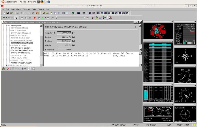
Here is what you should see on the screen during a successful boot programming:
1. I open a terminal and type: tail -f /var/log/messages to watch system messages
during this. Why? Because I need to know when the FTDI serial adapter cable is recognized
and when the Tiny is in USB boot mode that the computer recognizes it as a USB device
(i.e. ready for the USB programming).
So, first during boot loading. When I plug in the FTDI cable you should see this
in the log (or 'dmesg' command output):
Apr 19 09:52:47 ppzuav-desktop kernel: [ 2001.949231] usb 3-2: new full speed USB
device using uhci_hcd and address 6
Apr 19 09:52:47 ppzuav-desktop kernel: [ 2002.149803] usb 3-2: configuration #1
chosen from 1 choice
Apr 19 09:52:47 ppzuav-desktop kernel: [ 2002.152867] ftdi_sio 3-2:1.0: FTDI USB
Serial Device converter detected
Apr 19 09:52:47 ppzuav-desktop kernel: [ 2002.152903] /build/buildd/linux-source-2.6.22-2.6.22/drivers/usb/serial/ftdi_sio.c:
Detected FT232RL
Apr 19 09:52:47 ppzuav-desktop kernel: [ 2002.153167] usb 3-2: FTDI USB Serial Device
converter now attached to ttyUSB0
That tells me it is seen as /dev/ttyUSB0 If it is not unplug your other USB devices
and try again (i.e. unplug and re-plug in the FTDI cable) until it is seen as /dev/ttyUSB0.
If it just won't you can edit the Makefile but PM me I will give you those details
offline.
2. Plug in the adapter and then into the Tiny2.11 "download" connector. Ground should
be the very outmost wire and the Yellow wire (Rx) from the FTDI cable eventually
makes it to the 2nd most inward pin and the orange from the FTDI (Tx) makes it to
the very inward pin (Rx on the download connector).
3. Now connect (via jumper wire the negative pole on the PCB input (yes where you
plug in the power) and the other end to the 3rd inmost pin (next to the yellow wire
from the FTDI on the Tx on the "download" connector. This is directly routed to
pin 61 on the CPU inside the PCB. So, in effect you are setting that pin on the
CPU to the ground shared by everything on the Tiny2.11.
4. Power on (i.e. I use a 100.00 from Fry's 1A limiting power supply with jumper
to the + and - on the PCB at this stage). Your power supply if it has a meter showing
power draw should show 0.04A, then after and after resetting the power on the TIny
(without the jumper) it should read 0.06A for a Tiny2.11 with a GPS module and Antenna
and only the USB boot code.
5. The command to send the USB boot code into the Tiny2.11:
ppzuav@ppzuav-desktop:~/paparazzi3$ make upload_bl PROC=GENERIC
6. The output:
cd sw/airborne/arm7/test/bootloader; make clean; make
rm -f usbstack.a usbhw_lpc.o usbcontrol.o usbstdreq.o usbinit.o usbdescrip.o
rm -f bl.hex bl.elf crt.o startup.o printf.o console.o bootloader.o *.lst bl.dmp
bl.map
rm -f bl_ram.hex bl_ram.elf bl_ram.dmp bl_ram.map
.
.
<snip> <--yes I cut out a bunch of stuff that scrolls past
.
.
...copying
arm-elf-objcopy -O ihex bl_ram.elf bl_ram.hex
arm-elf-objdump -x --syms bl_ram.elf > bl_ram.dmp
lpc21isp -control sw/airborne/arm7/test/bootloader/bl.hex /dev/ttyUSB0 38400 12000
lpc21isp version 1.27
File sw/airborne/arm7/test/bootloader/bl.hex:
loaded...
converted to binary format...
image size : 7304
<snip again>
.
.
Read bootcode version: 2.12.0
Read part ID: LPC2148, 512 kiB ROM / 40 kiB SRAM (67305253)
Sector 0: .................................................. .............................................
Sector 1: .................................................. .........................
Download Finished... taking 6 seconds
Now launching the brand new code
ioctl get failed
ioctl set ok, status = 2
ioctl get failed
ioctl get failed
ioctl set ok, status = 186A0
ioctl get failed
Result is from above it did program then reset. This is why you see the "failed"
at the end is the code is uploaded but the CPU resets so you see the ioctl getting
those last messages as the CPU is not responding during this time (just a guess
correct me if I am wrong someone).
Maybe it's me but the above seems to imply a momentary grounding. Anyhow, cool,
bootloader loaded. Now if you read the programming page on the Wiki they tell you
how you likely don't even need to do that. However, remember, no one (at that time,
they do now) sells these assembled. So how many people reading that Wiki will have
had someone else do that for them? Yep, sort of wish the would re-order that Wiki
in the real order someone really programs these. The true order is this:
1. load the boot loader code
2. use the USB programming cable (custom made) to load the "Tunnel"
a. Plug in the USB cable w/adapter into the "usb" connector (with Tiny powered off).
Now power on the Tiny 2.11.
b. the output of the system messages file should show (or dmesg command):
Apr 19 10:44:34 ppzuav-desktop kernel: [ 5101.453832] usb 3-2: new full speed USB
device using uhci_hcd and address 7
Apr 19 10:44:34 ppzuav-desktop kernel: [ 5101.621497] usb 3-2: configuration #1
chosen from 1 choice
That above says my system (Linux) detected the Tiny2.11 as a new USB device
c. Now send this command to load the "tunnel":
make AIRCRAFT=PPZ1 tunnel.upload
d. The output:
cd sw/lib/ocaml; make PAPARAZZI_SRC=/home/ppzuav/paparazzi3 PAPARAZZI_HOME=/home/ppzuav/paparazzi3
make[1]: Nothing to be done for `all'.
cd sw/supervision; make
make[1]: Nothing to be done for `all'.
cd /home/ppzuav/paparazzi3/sw/tools; make
make[1]: Nothing to be done for `all'.
<snip>
cd sw/airborne; make PAPARAZZI_SRC=/home/ppzuav/paparazzi3 PAPARAZZI_HOME=/home/ppzuav/paparazzi3
TARGET=tunnel upload
/home/ppzuav/paparazzi3/sw/ground_segment/lpc21iap/lpc21iap /home/ppzuav/paparazzi3/var/PPZ1/tunnel/tunnel.elf
.
Found USB device
BootROM code: 2.12
Part ID: 0x0402FF25 (LPC2148, 512k Flash, 32k+8k RAM)
BootLoader version: 1.3
#
Starting software at 0x00004000
Cool, now the "tunnel" is loaded. This "tunnel" connects the GPS module to the serial1
port/connector on the Tiny2.11
NOTE: when in USB bootloader mode my Tiny2.11 is drawing 0.09A of current.
3. Using the cable used to load the boot loader, with a new custom adapter you have
to make (8pin not 7pin), to a different port (this time really serial1) you program
the GPS module to communicate with the paparazzi software correctly. This is called
u-center and I downloaded it from the u-blox website and installed it on my Linux
system (Yes, you can run "Windows" apps under Linux). So, now using u-center and
that cable on serial1 you upload a configuration file from the Paparazzi Wiki (under
GPS and configuring GPS).
*Now with the GPS configured we are ready to program the Tiny for aour aircraft.
Power off and power on the Tiny2.11 and you should see it is using 0.07A or 0.08A
of current with the "tunnel" loaded and running.
4. Using the USB programming cable you now (either with GUI or command line commands)
compile and upload an "airframe" file into the Tiny2.11 autopilot. Templates are
given but each file is unique to your aircraft. Now if you build one exactly like
one someone uses already you may find a template that requires only slight modification.
So, ok, I have the bootloader loaded, I loaded the "tunnel" and programmed the GPS...I
truly now believe I have a valid working ready to go Tiny2.11...ok, well someone
else does. I used a brand-new fresh from the Assembly company Tiny2.11 for that.
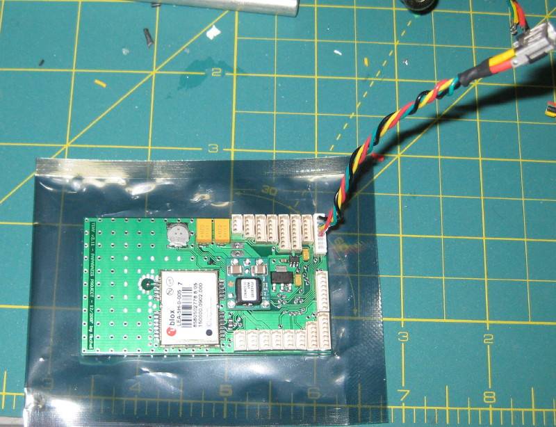
Next person who buys a Tiny2.11 from the Web Store (PPZUAV) gets this one that is
ready to go (i.e. putting it back in the anti-static bag ready to sell) see image
below the GPS is up and running and configured. I will reload the funjet1.xml aircraft
file into it.
Oh, FWIW that looks like this:
Found USB device
BootROM code: 2.12
Part ID: 0x0402FF25 (LPC2148, 512k Flash, 32k+8k RAM)
BootLoader version: 1.3
########################
Starting software at 0x00004000
SUCCESS!!!
12:15 AM
Here's the proof u-center (Windows App) installed fine and I used it to upload the LEA-4P config file from paparazzi.
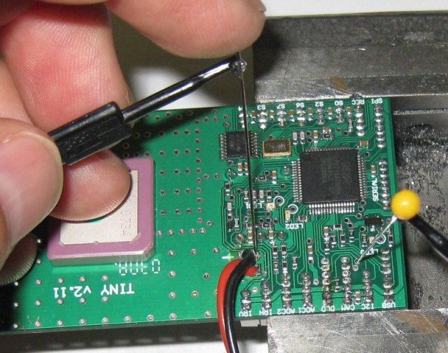
Here is how I set the P0.14 pin low at power on to tell the LPC2148 to wait for
boot programming. I had to hold this in place until after the programming was completed.
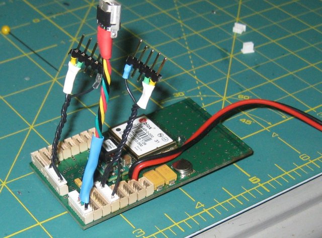
Tiny2.11 with the cables you will need. Left to right: GPS programming cable, USB programming cable, boot programming cable.
bmw330i
April 19, 2008
Lessons Learned (aka current status)
What I know now...moving forward...
Ok, so, today I have the following for my first aircraft project:
- One Tiny2.11 Autopilot with bootloader loaded and GPS configured
- One MicroJet FunJet with 300 motor and 25A ESC, 3-cell lipo, Futaba 7CAP Tx and
Berg 4L Rx (not yet converted for Paparazzi use yet)
- One MaxStream-Pro USB 2.4ghz Ground station RF Modem
- One MaxStream-Pro OEM Module with Wire Antenna RF Modem (For airplane)
- One Sparkfun Gyro Breakout board (ADXR based)
- One Dual Axis IR sensor and one Single Axis IR sensor
Where I am today, I have the above, I'm ready to start connecting and getting the
aircraft file edited correctly and installing all this. I hope to make a lot of
progress this weekend. One thing I know for sure now is this. Paparazzi is truly
impressive. As I learn and as I try and fail and try again I realize that in all
this the hardware is not the weak link. The software is not the weak link. The weak
link is between my ears. As I learn I simply find that what is posted just isn't
given as steps that work for me. Either they leave out some detail or they assume
something.
So, that's why I am doing this. I really do want people who truly want to do this
to not have to re-invent the wheel over and over again. People who would normally
give up hopefully can soon find that there are step by step instructions. So, trust
me, I know this post is not going to be that. But I am working on it. I have done,
and will do the following things to help others:
1. I now sell everything I use. If I need one I have 10 made. If they sell I have
more made. Sure, it's keeping me extremely busy but as long as it's not costing
me money I'm going to keep doing it. Go to the Wiki and there is a link for "Getting
Hardware" My Partner and I have a web store there.
2. I am going to keep very good notes. I am going to write something that a complete
Newbie Like myself can follow.
3. I will try and edit that Wiki as much as possible to fill in those blanks.
4. I will try my best to help anyone who asks for help. Even if that's pointing
you to someone else who maybe does have the answer.
Ya, trust me, I'm for real. I really am building this thing and I am not going to
quit. I have that much faith in this thing, in the Paparazzi Project. Why? Because
I had this same attitude when I downloaded, compiled and got a Beta version of Linux
working back in the mid 90s. It was just too cool and had so much promise. I'm going
to get this thing flying for many reasons...but mostly to again build something
cool and prove it can be done. Now if Paparazzi suddenly takes off here in the States
then so be it. I think the USA is a great place to have a new grass roots interest
in Aeronautics again.
References:
Paparazzi Wiki: http://paparazzi.enac.fr/wiki/index.php/Get_Hardware
12:16 AM
Last edited by bmw330i : Apr 19, 2008 at 01:01 AM.
dmgoedde
April 19, 2008
I hope your dedication and effort make it so that other people don't have the same hurdles!
12:23 AM
bmw330i
April 19, 2008
Me too. Really. If I could have bought all this RTF I would have done so. But,
I suppose like most things in life worth doing, I now wouldn't have wished it any
other way. I'm enjoying the challenge.
It's nice now to have the light-bulb in my head getting brighter. I really felt
like a complete idiot when I first started this project. I'm feeling a lot more
in control now. While it is fresh in my head I just figure I'll post what I've done
here.
Oh, Photos, ok, I do have photos. I'll put them either on my blog here or somewhere.
I don't see any way to attach them to this post yet...
12:55 AM
zlite
April 19, 2008
Did you try the prebuilt ones here?
http://www.onefastdaddy.com/catalog/
09:11 AM
bmw330i
April 19, 2008
See ROUND 2 above.
Here is a photo. Fortunately for me the Paparazzi does have very good documentation
of where things are. Just not in a true follow these exact steps, in the order to
do them, way...yet.
So, attached is also a picture with labels from the documentation.
The USB boot loader code has been loaded using the "download" connector (see the
other image with labeled connectors). Now all programming is done using this cable.
What you do is (High Level):
1. put Tiny2.11 in USB programming mode (i.e. power on with the USB cable connected)
2. send the aircraft file to the Tiny with either the GUI (paparazzi) or command
line:
make AIRCRAFT=ppzuav1 clean_ac ap.upload
Last few lines should (output) look like:
.
Found USB device
BootROM code: 2.12
Part ID: 0x0402FF25 (LPC2148, 512k Flash, 32k+8k RAM)
BootLoader version: 1.3
########################
Starting software at 0x00004000
That's it. Ready to fly well, that is if everything is configured properly...
Lower Level step by step:
1. Run the GUI '~/paparazzi3/paparazzi'
2. In the GUI select the funjet1.xml aircraft file.
3. there is a button to EDIT the file. In my case I bought the same things as the
person who created the funjet1.xml (except the chemical sensor) to make it easy
on myself.
4. Once edited there is a compile button
5. Once compiled you are ready to send the program to the Tiny2.11 power on the
Tiny2.11 with the USB cables connected. The Tiny2.11 will sense the 5v power coming
from the USB and go into programming mode and wait for the program.
6. Now click the UPLOAD button. The code will be sent to the Tiny2.11 and it will
automatically reset itself.
Now that is simplistic and best case. At this time all peripherals (RF Modem, Gyro,
ESC, servos, Receiver, IR sensors) can be connected to the Tiny and checked.
The reality is that you can do this likely your equipment will need to be "tuned"
for your aircraft. There is thankfully a page of documentation (documentation=Wiki)
For URL see my above posts where I give the URL to the Wiki...ok, here's the page:
http://paparazzi.enac.fr/wiki/index.php/Airframe_Configuration
All configuration of your aircraft is done via edits to XML files. What is interesting
to me about this is that at work I work with programmers who are Java/C++ programmers
and they do this same thing. All configurations for everything (and I'm talking
about Video over cell phones system here...very complex and millions of dollars
in software and equipment) are done the same exact way. Using an editor to configure
XML and that in turn generates configuration files and code. Just interesting that
half way around the world the Paparazzi Team is doing the same thing. That is nice.
If you would rather edit hard-coded values in your code that's fine. But XML is
easy to learn and if you learn it you learn a skill useful in not just Paparazzi
but other places as well.
10:12 AM
My Tiny2.11 ready for programming.
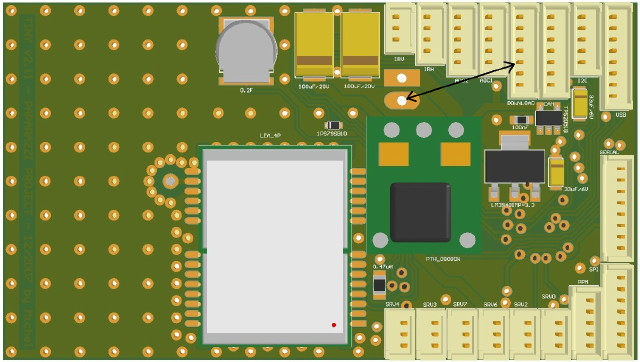
Another 2D view of the Tiny where you can read the connector labels. "download" is for the USB Boot Code Loading, and GPS programming (PPZUAV does this for their customers). I have drawn a line showing how you set P0.14 "low" (i.e. gro
bmw330i
April 19, 2008
Today I will work on the RF Modem Link
I'm learning myself all the XML variables (sure would be nice to have a table
somewhere with all the codes and values...hint hint to anyone in Paparazzi team
who knows them). Since my FunJet is using the same RF Modems (MaxStreamPro 2.4ghz)
it should be easy. For me it is not.
Today I focus on configuring my RF Modems. I have chosen to start with API mode
enabled. A little about what I have learned about these modems. They all communicate
with each other and form a "Mesh" network. Paparazzi can take advantage of this.
You can easily fly multiple aircraft at the same time controlled by the one ground
station using Paparazzi. A use I see is this: You could fly a blimp with a module
above you, since this module is seen by your aircraft (could be far away) your "mesh"
network is complete. Your ground stations is relayed the communication by the remote
aircraft and your aircraft now has a longer range possible. Or you could have an
aircraft circle overhead doing the same thing.
It appears this "mesh" networking was created for applications like: Utility companies.
Imagine all if every utility hookup in every home had one? This would create a mesh
network so that every house was connected to every other house (just the network
not the power). The utility company can now read all those meters wirelessly by
simply having a router on that network to their network or a server on that network
checking meters.
It seems that there are few places and a few steps here where order and values matter.
This is the confusing part for me because again the Wiki does not do a good enough
job (for me) to know exactly the XML code in exactly the order. So I am doing trial
and error today. I will post my results and the specific order and XML required.
What setup I want:
1. I want my base station USB modem to be 38400BPS
2. I want my Module to be 38400BPS
3. I want both using API mode
To verify I will run the GCS (Ground Control Station GUI) to see the data link between
them is sending data from the Tiny to the GCS application.
Steps so far:
1. Using the Maxstream utility deliverd on the CD ROM (and Windows <ugghhh working
on a Linux way to do this BTW>) I programmed the ground control station USB modem
for 38400BPS and API mode
2. I am reading the Wiki under airframe configuration to determine the commands
for my module and the order and syntax
...more to come as I do my trial/error...
10:47 AM
Last edited by bmw330i : Apr 19, 2008 at 05:10 PM.
bmw330i
April 19, 2008
FWIW:
A note about Windows/Linux. The paparazzi software runs on Linux. The instructions
and setup are all for a "debian" version of Linux. Not an issue in my opinion. My
favorite version Ubuntu is debian based. I have helped a few people now with installing
Paparazzi on Ubuntu Linux.
pat
My advice for Paparazzi is to get a decent laptop. There are many now under 1,000.00
and even some under 500.00 ones that will run Ubuntu (and therefore Paparazzi) just
fine. You can even do like I did with my latest Sony VAIO laptop and just install
Ubuntu alongside the Vista that came with it. The Ubuntu installer resized for me
the vista partition and I ended up with a laptop that allows me to choose which
to boot from at startup.
05:20 PM
bmw330i
April 22, 2008
Got the RM Modems working....
UPDATE:
Well, got the XBee-Pro Modems up tonight. I'm still confused by it though. I had
to set everything to 9600bps. Once I did that it worked. I had them set to 38400.
At that speed I could see when I launched the ground station the lites on the ground
station modem blink, then a rx light blink...then all but the power light go off.
Very weird.
But like I said, setting all to 9600bps and it all worked. I then quickly found
out that using "google fill" option triggers google to block your IP for a while.
This leaves me with the problem of how to get the cool background now. If Google
can't be used then what can be?
Tomorrow after work I will connect the Receiver and the IR sensors and get those
working.
I will upload a screen shot of my GCS showing the GPS is working and telemetry is
up and working.
01:38 AM
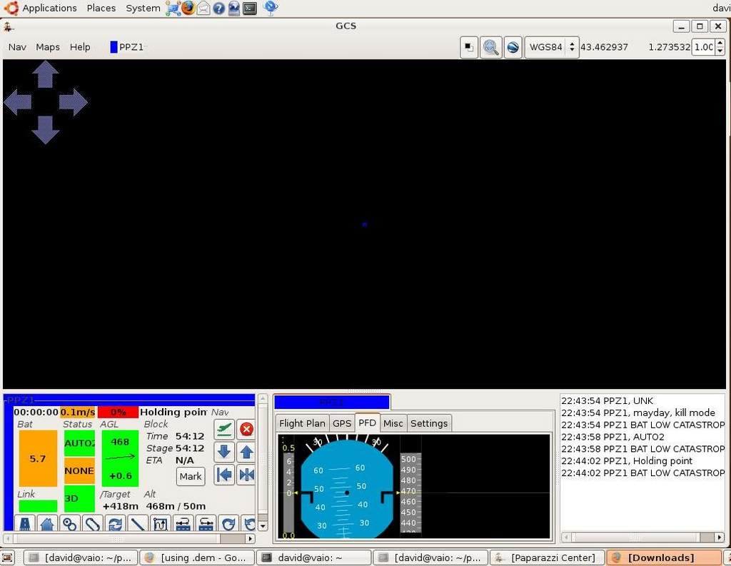
GCS screenshot, background fill is off. You can see the telemetry info on the bottom left.
bmw330i
April 25, 2008
Hey all,
Thanks for the comments. Remember, when it seems totally a blur I have been there.
I guess for some this is all routine but for the rest hopefully what I post will
be simple enough for us.
Latest update. Not a lot new to report. I had to build a few kits for people. Very
time consuming...So, it's a tedious task and the cost of these kits are truly for
my own time to make them.
So, that said (reason why not much progress lately) I did find I need to do some
more homework to get past the next stage. I have the following ready to hook up:
1. Receiver (Berg 4L)
2. XBee-Pro OEM Module (2.4ghz)
3. Two Hitech HS65 (elevons)
4. Tiny2.11
5. Generic ESC (25A)
6. 300 Motor
7. 3 cell Lipo
8. FunJet
9. Dual-IR sensor
The cabling is slowing me own. It's the Dual-IR sensor. I'm having a hard time sorting
out the pin1 on the board connector (on the Sensor). The Tiny2.11 has a good pinout
on the Wiki but not the Sensor. Often the pinout is viewed from the bottom of the
board not the top. Well when you plug it in your plugging it in from the top. The
info on the Wiki is not clear...so, as soon as I get that wire made I'll be ready
to plug it all together.
NExt Steps (after wiring up the Dual-IR sensor):
1. Calibrate all the above. This requires setting zeros for them, then their max
values. Then set min, max and neutrals...going to have to study the Wiki more and
the List (Paparazzi Development List) for info.
I have found that going to the Wiki is good first. Then go to the List and do a
search on terms like "GPS", "IR", or errors if you get them. Usually someone else
has had the same issue and you can find your answer there without bugging the members.
I have found if you do your homework and ask a good question that shows you did
some homework they are quick to respond to your requests.
Also as always feel free to ask me...
Oh, I'm at a Tibco Conference next week...not going to get anything new done next
week...just a head's up.
04:45 PM
bmw330i
May 12, 2008
Update: Been a while hasn't it? Well, here's what happened. One day about two
weeks ago something changed and I could no longer compile the Paparazzi airframe
configurations. Seemed something broke in the software. I don't remember exactly
if it was my cvs update command, my updating the packages or ? but all of a sudden
I was unable to run the commands to make and upload the software to the Tiny Autopilot.
I tried re-installing Ubuntu but I just could not get the dependencies worked out.
ivy-ocaml required this and that and the versions were too new...after a week I
gave up and installed Debian 4. This caused it's own issues in that Debian detected
about nothing and required manual config of everything (practically). I have two
laptops and Debian does not by default install the right (if any) Wifi drivers.
Add to that you have to add for WPA more stuff...and how do you do that without
connecting to a network? Grrr...
So about the time I'm getting Debian working I see someone posted about how Ubuntu
was working for them...ok, so I burn a new Ubuntu 8 Install CD, booted up, installed
it, then configured the Paparazzi Project repository for Ubuntu (Hardy), then sure
enough, it installed without any issues. Back in business with Ubuntu. So, I then
went to my 2 laptops, an iMac with Parallels running Linux in a VM, and my Desktop
(Dual Core) and all installed perfectly. Ubuntu 8 detected everything perfectly
and the Paparazzi Project software installed perfectly.
So, I'm back in business. It would have been nice to get some notification that
the packages were fixed other than seeing someone write about their install succeeded
but, like I said, it's open source. I don't expect it...just would be nice to know
when the software is changed and when it is fixed (i.e. fixed in that my running
it on Ubuntu works again).
NOTES/Lessons Learned:
1. Ubuntu is clearly miles ahead in detecting and configuring hardware properly
at install time.
2. Don't update from cvs unless you have a good reason. Don't update your packages
unless you have good reason. Things just might not work after you do so.
3. You have to be monitoring the email list to truly get updates on what's going
on. Don't wait for it to be posted on the Wiki or try and ask about it on IRC.
Time to continue. I hope this week to pick up where I left off...I will update when
I do.
09:10 PM
bmw330i
May 13, 2008
For the curious a step by step how I installed Paparazzi on Ubuntu 8.04
Well, here's the exact steps that works for getting a working Paparazzi Center
onto a freshly installed Ubuntu 8 system:
1. Download and burn an Ubuntu 8 Cd
2. Boot from it and follow prompts to get it installed. Since this is a "fresh"
install I used "Guided use whole disk" at the Partitioning step.
3. On Reboot Applied all Updates (the icon for update manager will notify you in
the top right corner, just open it and apply all updates, reboot).
4. Open Wiki Page detailing Paparazzi Install: http://paparazzi.enac.fr/wiki/index.php/Installation
5. basically add the Paparazzi "Ubuntu" Repository (Hardy). You can just add this
line to the /etc/apt/sources.list file:
Code:
# paparazzi project
 deb http://paparazzi.enac.fr/ubuntu hardy main
 # end paparazzi
NOTE: Must be "hardy" not gutsy branch, also the # are comments just for readablility
you can exclude them.
6. refresh the package list either with the refresh button in synaptic package manager
or this command:
Code:
sudo apt-get update
7. install paparazzi-dev, paparazzi-arm7 in SPM or:
Code:
sudo apt-get install paparazzi-dev paparazzi-arm7
8. Remove brltty:
Code:
sudo apt-get remove brltty
9. now get the source and compile by:
Code:
cd ~/ && cvs -z3 -d:pserver:anonymous@cvs.savannah.nongnu.org:/sources/paparazzi co paparazzi3
Code:
cd ~/paparazzi3 && make
10. Set permissions: As root copy "10-paparazzi.rules" as root from $PAPARAZZI_HOME/conf/system/udev/rules/
to /etc/udev/rules.d/
this is the command I used:
Code:
sudo cp /home/david/paparazzi3/conf/system/udev/rules/10-paparazzi.rules /etc/udev/rules.d/
11. Set env variables in .bashrc
Code:
vi ~/.bashrc (don't forget the period in front of bashrc)
add at the bottom:
Code:
# Paparazzi
 export PAPARAZZI_HOME=/home/< your login id here>/paparazzi3
 export PAPARAZZI_SRC=$PAPARAZZI_HOME
 export PATH=$PATH:$PAPARAZZI_HOME
Code:
:wq
:wq writes and exits in vi you can use any editor really I just like using vi
out of habit
NOTE: <your login id here means whatever you see if you type "whoami" goes there
without the <>
Test by running it. Exit the terminal, then open a new terminal. Then type: paparazzi
& <---the & means run it in the background.
That's what I did and do now and without any issues/errors.
02:35 PM
Last edited by bmw330i : May 13, 2008 at 02:46 PM.
bmw330i
May 21, 2008
Update:
I owe this thread an update.
Status:
Have two working Tiny2.11 ready to program for my two aircraft. One is an EasyStar
the other a FunJet.
EasyStar: Still in the box
FunJet: Airframe is together, servos in the wing, pushrods installed. Motor Mount
on, have the layout I wish for the autopilot, IR sensor (Dual Only), XBee Pro OEM
2.4ghz module, battery...have the Picoblade connectors on the Receiver, servos,
IR sensor (Dual) and ESC ... big note here...remove the power wire from the ESC.
You don't need it to be powering the Tiny as well. I forgot and the ESC got really
hot. I'm suprised I did not burn it up or the Tiny. I think I caught it in time.
Time now to:
- Get everything wired up and to the Tiny2.11 (Gyro, IR, ESC, Rx, Servos, Barometer
etc)
- Mount everything so Tiny2.11 can be powered on/off and programmed without removing
it or having to do any disassembly (i.e. remove parts from the plane).
- Need to set the neutrals for the IR sensors...basically the stuff on the Wiki
about tuning the airframe: http://paparazzi.enac.fr/wiki/index.php/Airframe_Configuration
I am also investigating SunMicrosystems (SunSpots) http://www.sunspotworld.com/
as a possible autopilot. They have built-in wireless, connector for external sensors
and best of all run a Java VM on a pretty speedy chip. The NetBeans IDE is free
as is much of the source for code that would work for an autopilot. My partner JB
is very good with Java so maybe we can get some traction with that and look into
that. To be honest I'm concerned about ivy-ocaml and the other bits that seem only
to be used in Paparazzi. Now ocaml I have heard of so I'm staying open minded. That's
why the SunSpot solution would be parallel not replacing Paparazzi "Tiny" based
solutions. Not yet.
Well that's my update. If we go the SunSpot direction I'll start a new thread on
that progress to keep this thread on the topic of Paparazzi Project build info.
I can say at this point I really have a good understanding of the Hardware, how
to program the boot code, the USB programming and the interaction with the GPS using
the tunnel. Next will be getting familiar with the other bits and flying. And learning
enough about the XML to add sensors not found in the default aircraft files given
as samples in the source.
Cheers,
David
06:27 PM
Copyright 2008 http://www.rcgroups.com/