RCX Internals
The RCX is programmable, microcontroller-based brick that can simultaneously
operate three motors, three sensors, and an infrared serial communications interface.
The brick is one of approximately 727 pieces of LEGO® set 9719 Robotics Invention
System.
This document is a description of the internals of the RCX, and is organized
into the following sections:
Please note that this not an official LEGO® document or web site. LEGO® is a
trademark of the LEGO Group [ http://www.lego.com/ ], which does not sponsor, authorize,
or endorse this document.
In addition, note that this document describes RCX internals as the author understands
them. While every effort has been made to ensure that the contents of this document
are accurate, the author does not guarantee that any portion of this document is
correct. The author cannot be held responsible for any consequences of the use or
misuse of the information contained in this document.
This document is currently a work in-progress.
Copyright © 1998, 1999 Kekoa Proudfoot. All rights reserved.
The base system for using the RCX consists of the RCX itself, an infrared transceiver,
and a PC. Additional components, such as motors, sensors, and other building elements,
combine with the base system to allow the creation of functional autonomous robotic
devices.
At the core of the RCX is a Hitachi H8 microcontroller with 32K of external RAM.
The microcontroller is used to control three motors, three sensors, and an infrared
serial communications port. An on-chip, 16K ROM contains a driver that is run when
the RCX is first powered up. The on-chip driver is extended by downloading 16K of
firmware to the RCX. Both the driver and firmware accept and execute commands from
the PC through the IR communications port. Additionally, user programs are downloaded
to the RCX as byte code and are stored in a 6K region of memory. When instructed
to do so, the firmware interprets and executes the byte code of these programs.
RCX
Pictures of a disassembled RCX. To remove the circuit board, open the RCX, remove
the four screws, remove the IR shield, then separate the front cover from the circuit
board. Release the two battery contacts from the battery side, then slide the circuit
board free. Do this at your own risk; if you're not careful there's a chance you'll
break something.
Patrick Gili reports that you can also twist the circuit board free without first
removing the battery contacts.
I've found that the negative battery contact is somewhat easier to release than
the positive one. By removing the negative contact first, then sliding the circuit
board free, I am able to remove the positive contact from the circuit board side
by inserting a small screwdriver in the slot between the contact and the battery
case and gently prying the contact outward and upward. I'm not sure if this technique
will work for others; it might be possible only because I have already disassembled
my RCX several times.
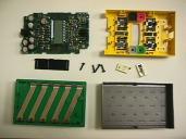
| The parts, from left to right, starting with the top row: circuit board,
front cover; IR shield, screws, battery contacts; battery case, battery
cover. Two removable plastic ribs are sitting on the battery case. (1x
image) |
 |
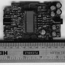
| The top of the circuit board. Two IR LEDs and an IR receiver are on
the left, an LCD is in the center, and several capacitors and an adapter
socket are on the right. The LCD is covering an LCD controller and a speaker;
above and below the LCD are the contacts for the four rubber keys. Twelve
clamps rise from the circuit board to mate with the input and output ports
on the cover. (1x image,
2x image, part numbers [
http://graphics.stanford.edu/~kekoa/rcx/list1.html ] ) |
 |
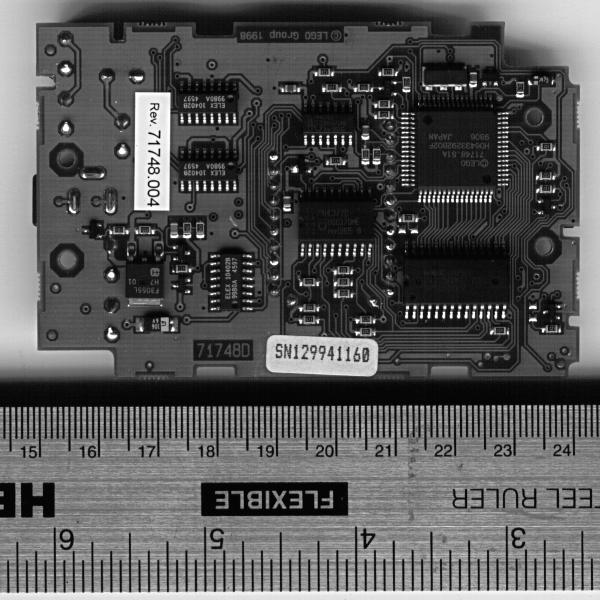
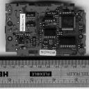
| The bottom of the circuit board. The large square chip is the microcontroller,
the chip below that is a RAM. The large chip in the middle is a bank of
flip flops, the small chip above that is a bank of NAND gates. Peter Phillips
[ peter@phillips.net ] sent word that the three identical chips on the left
half of the board are indeed motor controllers. (1x
image, 2x image, part
numbers [ http://graphics.stanford.edu/~kekoa/rcx/list2.html ] ) |
 |
IR Transceiver
It is also possible to disassemble the IR transceiver. Simply remove the four
screws and lift off the back cover, making sure to move the battery spring out of
the way.
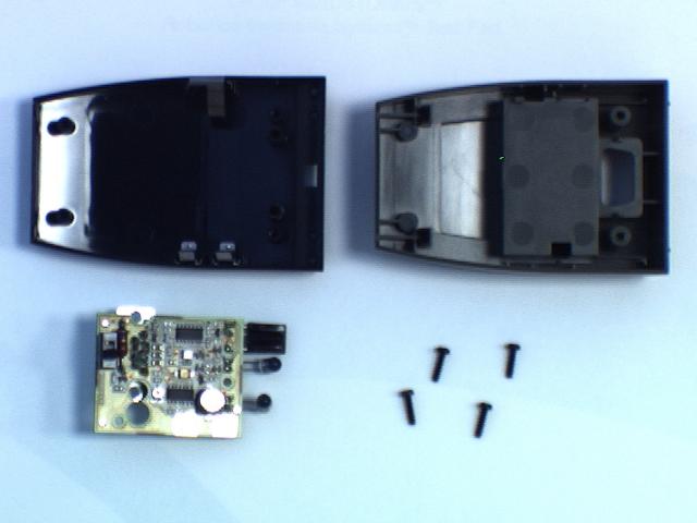
| IR transceiver parts. From left to right, starting with the top row:
front cover, back cover; circuit board, screws. The front cover doubles
as an IR filter. (1x image)
|
 |
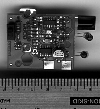
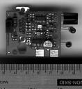
| The top of the circuit board in the IR transceiver. A switch and a 6.7
ohm resistor are on the left, the two chips in the middle are banks of NAND
gates, and the grey circle in the lower right is a voltage regulator. The
white rectangle below the chip in the upper middle is a green LED, and hanging
off the right side of the chip are the IR receiver and two identical IR
LEDs. The DB-9 serial connector is on the opposite side of the circuit board.
(1x image,
2x image) |
 |
Cables
The cable to connect the IR transceiver to your PC is a null modem cable that
contains six wires, of which only five are used. With the larger row on top, the
holes of each connector are numbered from right to left starting with the top row.
Pins inserted into these holes are joined by the cable to pins inserted into the
holes of the opposite connector as follows:
| Pin |
To |
Name |
Description |
| 2 |
3 |
RD |
Receive Data |
| 3 |
2 |
TD |
Transmit Data |
| 5 |
5 |
SG |
Signal Ground |
| 7 |
8 |
RTS |
Ready To Send |
| 8 |
7 |
CTS |
Clear To Send |
Pin 4 connects to pin 4 but is unused; pins 1, 6, and 9 have no connection.
The RTS/CTS signals are not used for flow control. Instead, they are used by
the PC to check whether or not the transceiver is connected. The transceiver wires
CTS and RTS together; the PC checks for the transceiver by asserting and deasserting
RTS. If it sees that CTS tracks RTS, then it assumes that the device sitting on
the serial port is the transceiver.
In case you're new to this sort of thing, to attach the IR transceiver to a Mac,
you can use the usual combination of a DIN-8 to DB-25 serial cable coupled to a
DB-25 to DB-9 adapter. If you try this, you might not be able to get the RTS and
CTS signals to function properly; this shouldn't be a problem if you're writing
or using custom software.
Encoding
The bit encoding and basic packet structure of the serial protocol was originally
described by Dave Baum [ dbaum@enteract.com ] in a message posted to the lego-robotics
mailing list. This section summarizes and expands on that description [ http://graphics.stanford.edu/~kekoa/rcx/protocol.html
].
My notes as of Nov 10 1998, which roughly outline some of the details of the
serial protocol, the byte code interpreter, and other parts of the rcx:
Basic packet format

[Contents Removed]
   Chris Osborn explained that ff is caused by tower powering down
   Confirmed this observation
|
Byte Code Interpreter

Tasks and subroutines

[Contents Removed]

Memory map

[Contents Removed]

Sources

[Contents Removed]


Loops

[Contents Removed]

Sounds

[Contents Removed]


Programs

[Contents Removed]
|
The table in this section gives a brief overview of the opcodes that make up
the RCX byte code and is an index into the RCX Opcode Reference [ http://graphics.stanford.edu/~kekoa/rcx/opcodes.html
], where more information about the opcodes can be found. An alphabetical opcode
index [ http://graphics.stanford.edu/~kekoa/rcx/opcodes.html#Alphabetical ] is also
available.
In the table below, the valid contexts of each opcode are listed under the Modes
heading. A P indicates a request sent from the PC to the RCX, an R indicates a reply
from the RCX to the PC, and a C indicates a command that may be used in byte code.
[Contents Removed]
A complete image of the ROM on board the microcontroller was obtained on Oct
1 1998. This section contains my notes on the ROM image, as of Apr 25 1999.
For now, you can find instructions for obtaining a ROM image here [ http://www.crynwr.com/lego-robotics/rom-image.html
].
On Oct 29 1998 I released some original replacement firmware. If you're interested
in this, the code is called first.s [ http://graphics.stanford.edu/~kekoa/rcx/first.s
], and the S-record data is called first.srec [ http://graphics.stanford.edu/~kekoa/rcx/first.srec
]. The firmware does nothing in particular except respond to the power key and light
up the display. After loading first.srec (either by using the OCX or by doing the
rename thing), you'll need to turn on your RCX with the batteries removed before
restoring the original firmware. Use first.srec at your own risk.
On Dec 15 1998 I started working on a separate ROM Reference document and a very
small ROM interface library that allows you to easily create programs that call
ROM functions from C compiled using GCC. The interface library was necessary to
test the reference document; however, I expect that it will make an excellent base
point for building up source for a non-Lego version of the 0309 firmware, should
anyone want to try that.
High level notes
   [Contents Removed]

Other notes
   Paul Haas was right about messages being grouped and parsed by lower 3 bits
   Tramm Nelson used to be reverse engineering the ROM from the firmware side
      He apparently also had gcc working, at least somewhat
      He also mentioned something about a web page, but gave no URL
   Matt Cross has also been doing interesting work with the firmware
      He mentioned switch on opcode in firmware
      Paul Haas had a few interesting comments what Matt had to say
   Other people offered advice on how to get a few tools set up
      Kenneth Dyke was the first person to describe how to compile gnu binutils
      Craig Trader was the first to describe how to use the disassembler
      I figured out how to use the assembler on my own
      Then I disassembled my code and edited the output bytes in emacs (!)
   Thanks to Matt Cross and Mark Salter I have gotten binutils to work
      H8300 binutils for IRIX are busted, I now run binutils under Solaris
      Technique is to assemble a .o, then link, as described by Mark Salter
      But Matt adds that you must convert branch target addresses to labels
         This fixes a sign extension problem with branch target addresses
   Allen Martin, Jon Andersson, and Bob Wind have all posted interesting info
      Allen came up with a method similar to Matt's for recompiling firmware
         He added the idea of testing reassembly by inserting nops
      Jon posted some rough notes from looking at the ROM disassembly
      Bob Wind posted a description of cc00 firmware data structure
         I came up with a similar list independently, which is included below
   Matt Cross found out some interesting things about the 070c ROM routine
      Matt explained it is a state machine
      My conclusion is that it drives the RCX when firmware is not loaded
   Markus Noga has been doing a lot of interesting work with GCC
      He is also looking into interesting ways to bypass/rewrite ROM routines
         A bit lower level than I imagined going
         An interesting way to extend things
   I know I'm forgetting somebody here
   Vadim mentioned I had used 0x80 instead of 0x08
      Fixed this
      Also fixed mention of lsb when I meant lower 3 bits
|
Notes on addresses:

ROM vectors/data:
[Contents Removed]

ROM code:
[Contents Removed]

ROM data:
[Contents Removed]

Firmware code:

[Contents Removed]

Firmware data - [Contents Removed]

ROM data: (okay to use when firmware loaded)

[Contents Removed]

More ROM data: (volatile when ROM functions in use)
[Contents Removed]

ROM data in on-chip RAM:
[Contents Removed]

Control registers:

[Contents Removed]

Interesting firmware notes:

[Contents Removed]

Pages of interest:

[Contents Removed]

Stack pointer is set here:

[Contents Removed]
|
Notes on routines:

[Contents Removed]
|
Hardware notes:

[Contents Removed]

Ralph Hempel first suggested that port 5 bit 2 puts RAM into low power mode
    He discovered the problem debugging power_off with a stack in off-chip RAM
    Verified function of port 5 bit 2 by not powering down RAM during power off
|
I've written a few tools for the RCX. They are described in detail on a separate
page [ http://graphics.stanford.edu/~kekoa/rcx/tools.html ]. In particular, you
will find a program to send messages to the RCX and a program to download a firmware
file to the RCX.
The tools are distributed as C source code. They are intended for Unix machines.
In particular, they are known to compile and run under Linux, Solaris, and IRIX.
The official LEGO® MindstormsTM web page is
http://www.legomindstorms.com.
More RCX information, and details about how to join the lego-robotics mailing
list, are available at http://www.crynwr.com/lego-robotics/. Many thanks to Russell
Nelson [ nelson@crynwr.com ], who coordinated the reverse engineering effort with
this web site and mailing list.
A Perl script for sending messages to the RCX is at http://hamjudo.com/rcx/.
One of the tools I use is a C program [ http://graphics.stanford.edu/~kekoa/rcx/tools.html
] with similar functionality, and I must say that I've grown accustomed to the speed
of typing raw hex at the RCX from a command line. Links to a number of other tools
for communicating with the RCX can be found at http://www.crynwr.com/lego-robotics/.
A document describing SPIRIT.OCX, an ActiveX control which can be used to manipulate
the RCX, is available at http://www.holdren.com/scott/legos/. Also, instructions
for wrapping the OCX with C++ code are at this location [ http://www.geocities.com/SiliconValley/Hills/8306/Lego/mindprog.html
].
Dave Baum [ dbaum@enteract.com ] is the author and maintainer of a simple RCX
compiler and a few other utilities. You can find more information at http://www.enteract.com/~dbaum/lego/nqc/.
If these tools were available for my platform, I'd almost certainly use them.
Finally, I gave a talk on reverse engineering the RCX on Oct 7 1998 for the EE380
seminar at Stanford. While I don't describe a lot of reverse engineering methodology
in this document, I did describe good amount of it in my talk. My slides are available
online [ http://graphics.stanford.edu/~kekoa/rcx/talk ].
An unrelated link to the Unofficial Quake 3 Map Specs [ http://graphics.stanford.edu/~kekoa/q3/
], so search engines will index it.
| Copyright © 1998, 1999
Kekoa Proudfoot. All rights reserved. |
kekoa@graphics.stanford.edu
|