Novell
1996
This primer explains basic networking concepts and technology and also introduces networking terminology to help you better understand the uses and benefits of Novell® products. We believe this primer provides a fairly thorough foundation for understanding any network-related discussion. Fundamentally understanding networking technology illuminates its potential. It also underscores the viability of a smart global network, which will provide virtually everyone a nearly instantaneous digital link to other network users and to seemingly endless information and services.
A computer network is a collection of devices that can store and manipulate electronic data, interconnected in such a way that network users can store, retrieve, and share information. Commonly connected devices include microcomputers, minicomputers, mainframe computers, terminals, printers, various data storage devices, and a host of other equipment.
In the near future, as the smart global network becomes a reality, numerous other types of devices will become network connectable, including such home devices as interactive TVs, videophones, and environmental control systems. What's more, the devices in your home will eventually give you two-way access to a worldwide network, the Information Superhighway.
You can store virtually any kind of information on a computer network, including textual information such as letters and contracts, audio information such as voice messages, and visual images such as facsimiles, photographs, medical x-rays, and even video. And, on a network, you can very quickly and easily transmit this information to other people.
The reasons for networking computers are compelling. Having a computer network enables you to combine the skills of different people and the power of different equipment, regardless of the physical locations of the people or the equipment, and by doing so, to benefit enormously.
A well-designed computer network enables users to instantaneously and effortlessly collaborate and view, change and exchange information.
For example, a managing editor, writers, associate editors, and artists may need to work together on a publication. With a computer network, they can share the same electronic files, each from his or her own computer, without copying or transferring files. If the applications they are using feature even basic integration with the network operating system, they can perform such tasks as opening, viewing, and printing the same file simultaneously.
With network-integrated applications, of which you will learn more later, network users will be able to collaborate with an ease and an effectiveness never before experienced. For example, multiple users will be able to engage in real-time teleconferencing, talking face-to-face, while simultaneously editing the same document, adding and deleting notes and comments, and viewing each other's notes as they are being created. And, they will be able to do this without having to worry about accidentally ruining or deleting the work of others.
To be able to collaborate electronically from widely separate physical locations has significant advantages. It frees people from spending considerable time and effort traveling, from communicating by less effective means, and from reconciling the differences in multiple versions of information. In short, it frees them from redoing work they would have done correctly in the first place if they had had up-to-date information and instructions.
If you choose an open networking environment, this adds another dimension to the information-sharing capabilities inherent in computer networking. Open networking products enable users to work on the type of computer best suited to the job they must do, without placing restrictions on their file-sharing capabilities.
The design of any particular computer can make it well suited for some tasks and not as well suited for others. In an open environment, you can combine many kinds of computers to take advantage of the special strengths of each type of machine. For example, Novell network users can use IBM PCs running Windows or DOS, Macintosh computers running a version of the Macintosh operating system, Sun workstations running the UNIX® operating system, and many other types of computers, all on the same network. Scientists, secretaries, doctors, lawyers, writers, editors, artists, engineers--everyone can use the type of computer equipment best suited to the type of work he or she does, yet each can still easily share information with everyone else.
A very important reason for having a computer network is that it enables users to share equipment.
Equipment sharing has significant benefits. It enables you to buy equipment with features that you wouldn't otherwise be able to afford and to ensure that the equipment is used to its full potential. A correctly implemented network can result in both increased productivity and overall lower costs.
For example, suppose you had a number of unconnected computers. People using these computers would not be able to print unless you purchased a printer for each computer or unless users manually transferred files from computers without printers to those with printers. In choosing between these alternatives, you would be choosing between significant expenses for hardware or significant expenses for labor.
But networking the computers would give you other alternatives. Because all users could share any networked printer, you would not need to buy a printer for every computer. Therefore, rather than buying numerous inexpensive printers, none of which had top-end productivity features and all of which would sit idle most of the time, you could buy a few inexpensive printers and a few printers with top-end productivity features. The more powerful printers might be able to print twenty times the number of pages per minute that inexpensive printers can print. And, the more powerful printers might also be able to print in color and to sort, staple, or bind any number of pages into multiple documents.
On a Novell network, all users could share the various printers, accessing whichever printer was most appropriate for the job they were doing. The network software would enable users to print whenever they wanted. The network would print documents in the order they were received, on the printer the user intended. Users would be able to change the order in which documents were to be printed and where they were to be printed whenever necessary.
By selecting the right mix of printers and allowing each network user appropriate access to them, you would have enough printing power to take care of the needs of all users, you would ensure that expensive equipment was not standing idle, and you would provide users with the latest, most powerful productivity features, freeing them from many tasks they would otherwise have to do manually--all for a significantly lower cost than if you were to buy separate printers for a number of unconnected computers.
A network enables you to share any networkable equipment or software and realize the same benefits that you would enjoy from sharing printers. On a network, users can share modems, data storage devices such as hard disks and CD-ROM drives, data backup devices such as tape drives, E-mail systems, facsimile machines, and all networkable software.
One of the most powerful things a network user can do is simultaneously use the processing power of two or more computers. One method of doing this is remote login. A user working on his or her own computer can simultaneously log in to and use the processing power of another person's computer. This makes use of equipment that would otherwise be sitting idle, and it can be done even on computers that are already in use but still have processing power available.
A second method of simultaneously using the processing power of two or more computers is parallel processing, which means distributing the processing required to accomplish one large task to many computers. Some programs are too big to run on individual microcomputers or would run too slowly, but can easily be run at lightning speed when distributed for parallel processing by several networked machines.
There are other advantages to computer networking that may be even more important than instantaneous, coordinated information sharing and equipment sharing. The best networks have extremely powerful security features that enable you to exercise flexible control of who will have access to sensitive data and equipment.
If you choose a networking company with a full suite of products, you will be able to connect computing equipment at distant geographic locations into one cohesive network. As a result, you will be able to pass critical data to multiple locations anywhere in the world, almost instantaneously.
Integrated, flexible information sharing; instantaneous information transfer; lower equipment costs; flexible use of computing power; secure management of sensitive information--these are the benefits of computer networking. And, these benefits help us produce the results we all are looking for: increased efficiency, productivity, and profitability.
The purpose of computer networks is to enable users to store and manipulate data so it can be stored, retrieved, and shared. To understand how available technology enables us to do this, we need to define a few terms and understand some basic concepts.
Although we routinely use the terms "data" and "information" interchangeably, they are not technically the same thing.
Data are entities that convey meaning. Computer data is stored as a series of electrical charges arranged in patterns to represent information. In other words, data refers to the form of the information (the electrical patterns). It is not the information itself.
For our purposes, information will mean decoded data, in human-readable form. In other words, information is the real-world, useful form of data. For example, the data in an electronic file might be decoded and then displayed on a computer screen or printed onto paper as a business letter.
To store meaningful information as data and to retrieve the information, we use an encoding scheme--we agree on a series of electrical patterns that will represent each of the discrete pieces of information we want to store and retrieve. For example, we agree that a particular series of electrical patterns will represent the alphabetic character "A." There are many encoding schemes in use. One common data-encoding scheme is ASCII code; an appendix at the end of this primer gives a description of the ASCII data code.
To actually encode information into data and later decode that data back into information, we use electronic devices, one of which is the computer, that generate electronic signals. Signals are simply the electric or electromagnetic encoding of data. Various components in a computer enable it to generate signals to perform the encoding and decoding task.
At the most general, conceptual level, to have a computer network we need only three components. First, we need a data code. Next, we need computers and auxiliary devices to encode information into data signals and to decode data signals back into information. Finally, we need the means to transfer the signals between the computer devices.
Let's suppose we've agreed on a coding scheme and we have several computers that are all capable of encoding and decoding the information we want to save.
Now, to have a computer network, we need only the means of transferring the generated signals between the computers. To transfer signals between the computers, we need two things: (1) a transmission medium to carry the signals and (2) devices to propagate (send) and receive the signals.
Electrical signals are generated as electromagnetic waves (analog signaling) or as a sequence of voltage pulses (digital signaling). To be propagated (sent) from one location to another, a signal must travel along a physical path. The physical path that is used to carry a signal between a signal transmitter and a signal receiver is called the "transmission medium."
There are two types of transmission media: guided media and unguided media.
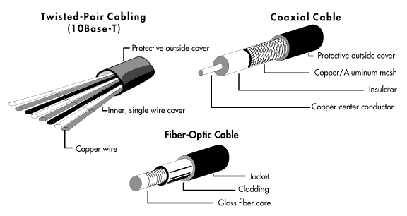
Guided media are manufactured so that signals will be confined to a narrow path and will behave predictably. Commonly used guided media include twisted-pair wiring, similar to common telephone wiring; coaxial cable, similar to that used for cable TV; and optical fiber cable.
Figure 1: Common guided transmission media
Unguided media are natural parts of the existing environment that can be used as physical paths to carry electrical signals. Earth's atmosphere and outer space are examples of unguided media that are commonly used to carry signals. These media can carry such electromagnetic signals as microwave and infrared light waves.
Regardless of the type of medium, the network signal is transmitted through it as some kind of waveform. When transmitted through wire and cable, the signal is an electrical waveform. When transmitted through fiber-optic cable, the signal is a light wave, somewhere in the spectrum of visible or infrared light. When transmitted through Earth's atmosphere or outer space, the signal can take the form of waves in the radio spectrum, including VHF and microwaves, or it can be light waves, including infrared or visible light (for example, lasers).
When planning a computer network, planners choose a transmission medium, or a combination of media, based on the physical circumstances involved in building the network and the reliability and data-handling performance required of the network. The objective is to keep costs to a minimum yet provide all parts of the network with the required reliability and performance.
For example, if you needed to build a network consisting of two subnetworks located in separate buildings several miles apart, you might use two or more transmission media. If you did not require the same level of performance on both subnetworks, you might use a different type of wire or cable as the transmission medium on each.
To connect the two subnetworks across town and ensure a reliable connection even in rain and fog, you might use a third medium, Earth's atmosphere, and connect the subnetworks through a microwave link. Or, you might use a T1 or T3 connection. T1 and T3 are dedicated lines (basically special telephone lines) that support high-speed communications. They can be leased from private companies that specialize in providing communication services.
Once you have a transmission medium, you need devices that can propagate signals across the medium and devices that can receive the signals when they reach the other end of the medium. There are a number of such devices used in computer networking. Such devices are designed to propagate a particular type of signal across a particular type of transmission medium. Transmitting and receiving devices used in computer networks include network adapters, repeaters, wiring concentrators, hubs, and infrared, microwave, and other radio-band transmitters and receivers.
A network adapter is the hardware installed in computers that enables them to communicate on a network. Network adapters are manufactured in a variety of forms. The most common form is the printed circuit board, which is designed to be installed directly into a standard expansion slot inside a microcomputer. Other network adapters are designed for mobile computing. They are small and lightweight and can be connected to standard connectors on the back of portable (laptop and notebook) computers so that the computer and network adapter can be easily transported from network to network.
Network adapters are manufactured for connection to virtually any type of guided medium, including twisted-pair wire, coaxial cable, and fiber-optic cable. They are also manufactured for connection to devices that transmit and receive visible light, infrared light, and radio microwaves, to enable wireless networking across the unguided media of Earth's atmosphere and outer space.
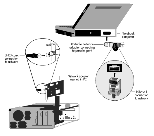
The connection hardware used to make connections between network adapters and different transmission media depends on the type of medium used. For example, twist-on BNC connectors are commonly used for connection to coaxial cable, while snap-in telephone-type jacks are ordinarily used for connection to twisted-pair wiring. Figure 2 shows two different types of network adapters connected to different computers and media, using different types of connectors.
Repeaters are used to increase the distance over which a network signal can be propagated.
As a signal travels through a transmission medium, it encounters resistance and gradually becomes weak and distorted. The technical term for this signal weakening is "attenuation." All signals attenuate, and at some point they become too weak and distorted to be reliably received. Repeaters are used to overcome this problem.
A simple repeater is a device that receives the network signal and retransmits it at the original transmission strength. Repeaters are placed between other transmitting and receiving devices on the transmission medium, at a point where the signal will not have attenuated too much to be reliably received.
Repeaters are often built into other, more complex networking devices. For example, virtually all network adapters have built-in repeaters. Manufacturers of network adapters often manufacture standalone repeaters to be used specifically with their adapters.
Wiring concentrators and hubs provide a common physical connection point for computing devices in microcomputer networks. (We limit this discussion to devices used for making physical connections. The term "concentrator" can mean something different in a mainframe or minicomputer environment.) Most hubs and all wiring concentrators have built-in repeaters and thus perform the same signal reception and retransmission function as a repeater (along with other functions).
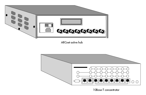
Traditionally, hubs and wiring concentrators have been proprietary, standalone hardware; there are a number of companies that manufacture such hubs and concentrators. More recent hub technology is based on hub cards and software that work together in a standard computer.
Figure 3 shows two common hardware-based connection devices: an ARCnet active hub and an Ethernet 10Base-T concentrator. A software-based hub/router is not shown.
Figure 3: ARCnet active hub and Ethernet 10Base-T concentrator.
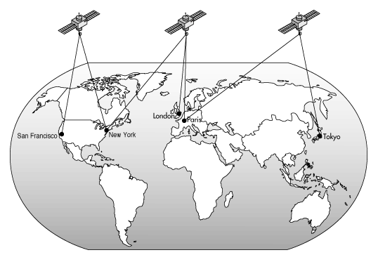
Microwave transmitters and receivers, especially satellite systems, are commonly used to transmit network signals over great distances. A microwave transmitter uses the atmosphere or outer space as the transmission medium to send the signal to a microwave receiver. The microwave receiver either relays the signal to another microwave transmitter, which sends it to another microwave receiver, or the receiving station translates the signal to some other form, such as digital impulses, and sends it along on some other suitable medium. Figure 4 shows a satellite microwave link.
Figure 4: Satellite microwave link
Infrared and laser transmitters are similar to microwave systems. They use the atmosphere and outer space as the transmission media and require a line-of-sight transmission path. The major difference is that they transmit light waves rather than radio waves. Infrared and laser transmissions are useful for signaling across short distances where it is impractical to lay cable--for instance, when networks are at sites a few miles apart. Because infrared and laser signals are in the light spectrum, rain, fog, and other environmental factors can cause transmission problems.
Modems convert digital (computer) signals to analog (audio) signals, and vice versa, by modulating and demodulating a carrier frequency. The most common modems transmit and receive data across ordinary voice-grade telephone lines.
A transmitting modem converts (modulates) the encoded data signal to an audible signal and transmits it. A modem connected at the other end of the line listens to the audible signal and converts it back into a digital signal (demodulates it) for the computer on the receiving end of the communication link. Modems are commonly used for inexpensive, intermittent communications between geographically isolated computers and a main network.
As we mentioned previously, each transmitting and receiving device is designed for a particular transmission medium.
Now that you know what a transmission medium is and have been introduced to transmitting and receiving devices, it will be useful for you to know what a topology is and how it is often different from a network's physical layout.
Physical layout is just what its name implies: It is the way the physical connections between computers are arranged when you look at them. For example, in a network connected by some type of wiring, it is the pattern of the wired connections.
Topology, on the other hand, refers to the "logical layout" of the network wiring. In more exact terms, it is the way in which the end points of the network are electronically connected. The physical layout and the topology of a network are often not the same, and, because the topology of a network is commonly used to describe its type, it is important to understand what a topology is.
To illustrate the point, let's first look at the physical layout of a sample network. In Figure 5, the various computers in the network are connected by wiring to a concentrator in a physical star pattern. The actual wiring is shown as the solid line between computers. When you look at the layout of the wiring, you can easily identify the physical layout of this network: It's a physical star.
Figure 5: Ring topology network connected as a physical star
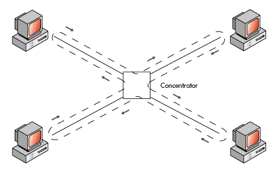
Now let's look at the topology of the network. Remember, the topology is the way in which the end points of the network are electronically connected. The electronic connection of this network is shown by the dashed line. The arrows beside the dashed line show the path that the electrical signal travels in this network. If you trace the path of the signal, you will find that it travels in a clockwise direction, around a closed path (a ring). This topology is called a ring (it will be described in more detail in the next section).
How can the signal travel in a circular path when confined to the physical layout? There are various means of accomplishing this. There could be two separate wire paths on the inside of the cable. Or, there could be one wire path with the inbound and outbound signals traveling on the same wire but on a different frequency. However, it's not the method that's important here. And, it's not important that the electronic path is not perfectly circular or oval. What's important is that the signal travels around a closed path, in one direction.
When it comes to laying out cable, virtually all networks are physically connected in either the star or bus pattern, with the star pattern being most popular, especially recently. The reasons for using these two physical layouts are simple: Installing cable in these patterns saves cable, initial installation is relatively easy, and it's easy to add workstations later.
There is considerably more variety (and parity) in the use of networking topologies. Network designers have worked out three basic topologies, each of which has distinct advantages in specific situations. Figure 5 illustrates the ring topology. Figures 6 and 7 show the other two basic topologies, the bus and the star. As you look at these topologies, remember that the diagrams represent logical, not physical, connections.
In the ring topology, to which you have already been briefly introduced, the signal path between the network workstations is a closed path (a ring). The signal is transmitted around the ring in one direction. Each workstation receives the signal from the workstation before it and repeats the signal for the next workstation. When a workstation transmits data on the ring, it gives the data the address of some other workstation. The data is circulated around the ring through each workstation's repeater until it reaches the workstation to which it is addressed and is copied. When the signal returns to the workstation from which it was originally transmitted, it is removed from the ring.
Ring topology schemes almost always rely on workstations taking turns transmitting. This turn taking is controlled by use of a "token." A workstation can transmit only when it is in possession of the token. Furthermore, it can have the token only a limited time before it must pass the token to the next workstation. This scheme ensures that all workstations get adequate access to the transmission medium. IBM's Token-Ring network is a well-known ring topology network.
In the bus topology, all workstations are attached to a linear transmission medium that has two ends. When a workstation transmits a signal, it travels in both directions from the workstation to both ends of the cable (bus), where it is absorbed (removed from the cable) by appropriate electronics. Because the signal travels to all parts of the cable, every workstation receives it. The workstation to which the data is addressed copies the data as the signal goes by.
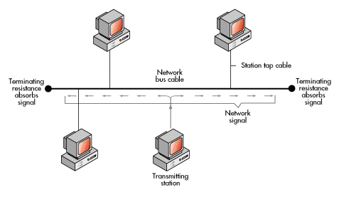
Bus topology schemes rely on either token passing or contention to establish which workstation has access to the transmission medium. The contention scheme works like a telephone party line. A workstation "listens" to determine if any other workstation is transmitting on the medium. If another workstation is on the medium, the workstation waits a predetermined time and listens again to see if the medium is still busy. When the medium is not busy, the workstation transmits. If two workstations transmit at the same time and there is a "collision," both workstations detect the collision and wait a random amount of time before attempting to resend.
The bus topology has a variant called the "tree topology." It consists of two or more main (bus) cables emanating from a central point.
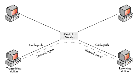
In the star topology, each workstation is attached to a common central switch. When one workstation transmits a signal to another workstation, the central switch routes the signal from the sending workstation to the receiving workstation; the switch makes decisions regarding destination addresses and switches the signal from line to line.
Again, it is important to note that what the network cabling layout looks like probably won't tell you what it acts like electronically. You could have a ring topology with either a linear or star physical layout. Or, you could have a bus topology with either a linear or star physical layout. Or, you could have a star topology with a star layout.
In general, a network's physical layout will be determined by the physical layout of the site at which it must be installed and by access to wiring paths. A network's topology will be determined by the type of applications to be run on the network and the network performance required to run them most successfully.
Now that we've seen the hardware pieces that make up a network and discussed the difference between physical layout and topology, let's connect some hardware to form a simple network. Figure 8 shows some of the hardware items we have discussed, connected to form a very basic computer network.
Figure 8: Various networking hardware connected to form a simple network
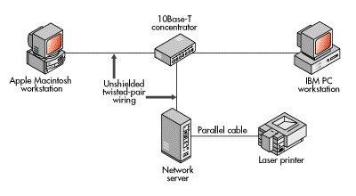
The network in this illustration includes the following components: three computers connected through a 10Base-T concentrator by means of unshielded twisted-pair wiring; three Ethernet 10Base-T network adapters, one installed inside each of the computers; and a laser printer that is connected to one of the computers.
The computer at the bottom center of the illustration is a network server; it controls the network (details will be covered in a following section). The other two computers are workstations. The workstations use the network under the control of the network server. One workstation is an IBM PC and the other is an Apple Macintosh computer.
The 10Base-T concentrator serves as a common connection point for the three computers; it repeats network signals.
The lines between the different components of the network represent the transmission medium, which is twisted-pair wiring. This network is connected in a star layout, but it happens to be a bus topology that uses a contention scheme as the means for workstations to get access to the transmission medium.
The printer in this network is connected directly to the server by means of a parallel interface cable, which is a standard connection method. The server accepts print jobs from either workstation and sends the jobs through the parallel interface cable to the printer. This is the simplest way to enable both workstations to use the printer. There are other ways to connect printers to a network, including attaching them to a computer set up as a dedicated print server or connecting them to a computer that runs special software enabling it to function as both a workstation and a print server.
Once you have the hardware we've discussed so far, you can start connecting the various pieces into a network.
But simply connecting hardware doesn't make a computer network. Even though the hardware is capable of generating signals and transmitting them across a medium, it must be told when and how to do this. There must be network communication software to tell the hardware when and how to transmit. The software and hardware on all parts of the network must work together to enable the transmission of data from one networked computer to another. We'll explore various networking software a little later. First let's look at the communication model that is the basis for controlling data transmission on computer networks.
To guarantee reliable transmission of data, there must be an agreed method that governs how data is sent and received. For example, how does a sending computer indicate which computer it is sending data to? And, if the data will be passed through intervening devices, how are these devices to understand how to handle the data so that it will get to the intended destination? And what if the sending and receiving computers use different data formats and data exchange conventions--how will data be translated to allow its exchange? These are only a few of the questions that must be answered before data can be reliably transmitted and received across a computer network.
Understanding the Open Systems Interconnection (OSI) model will allow you to understand how data can be transferred between two networked computers, regardless of whether they are on the same network, or are the same type of computer, or use the same data formats and exchange conventions.
The OSI model was developed by the International Standards Organization (ISO) as a guideline for developing standards to enable the interconnection of dissimilar computing devices. It is important to understand that the OSI model is not itself a communication standard. In other words, it is not an agreed method that governs how data is sent and received; it is only a guideline for developing such standards.
It would be difficult to overstate the importance of the OSI model. Virtually all networking vendors and users now understand how important it is that network computing products adhere to and fully support the networking standards the model has spawned. The reasons are logical.
First, when a vendor's products adhere to the standards the OSI model has spawned, connecting those products to other vendors' products is relatively simple. Conversely, the further a vendor departs from those standards, the more difficult it becomes to connect that vendor's products to those of other vendors. Second, if a vendor were to depart from the communication standards the model has spawned, software development efforts would be very difficult because the vendor would have to build every part of all necessary software, rather than often being able to build on the existing work of other vendors.
The first two problems give rise to a third significant problem for vendors: A vendor's products become less marketable as they become more difficult to connect with other vendors' products, especially if the introduction of the vendor's products lags behind the general marketplace.
Now, keeping in mind the purpose of the OSI model, let's take a look at its structure.
Because the task of controlling communications across a computer network is too complex to be defined by one standard, the ISO divided the task into seven subtasks. Thus, the OSI model contains seven layers, each named to correspond to one of the seven defined subtasks.
Each layer of the OSI model contains a logically grouped subset of the functions required for controlling network communications. The seven layers of the OSI model and the general purpose of each are shown in Figure 9.
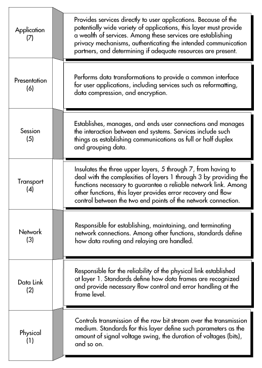
National and international standards organizations have developed standards for each of the seven OSI layers. These standards define methods for controlling the communication functions of one or more layers of the OSI model and, if necessary, for interfacing those functions to the layer above and below.
A standard for any layer of the OSI model specifies the communication services to be provided and a protocol that will be used as a means to provide those services. A protocol is a set of rules that two network workstations must follow (at any OSI layer) to communicate. It consists of the control functions, the control codes, and the procedures necessary for successfully transferring data.
For every layer of the OSI model, there is more than one protocol standard. This is because a number of standards were proposed for each layer and because the various organizations that defined those standards--specifically, the standards committees inside these organizations--decided that more than one of the proposed standards had real merits. Thus, they allowed for the use of different standards to satisfy different networking needs.
Using the seven layers of the OSI model, we can explore more fully how data can be transferred between two networked computers. Figure 10 uses the OSI model to illustrate how such communications are accomplished.
Figure 10: Networked computers communicating through the OSI model
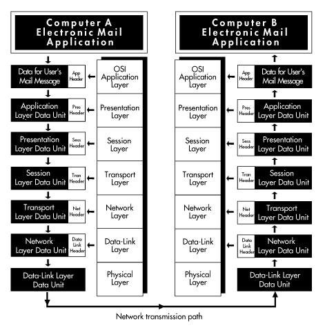
Our figure represents two networked computers, each of which is running various pieces of software (most not shown). Running together, the various pieces of software implement the seven OSI layers. These computers are identical: They are running identical software, and they are using identical protocols at all OSI layers. Above the OSI application layer, each computer is running an E-mail program. The E-mail program enables the users of the two computers to exchange messages. Our figure represents the transmission of one brief message from computer A to computer B.
The transmission starts with the user of computer A pressing a key to send a mail message to the user of computer B. The E-mail application is designed to talk to the OSI application layer--it knows the proper protocol for doing so. The E-mail application transfers the message to the OSI application layer. Using the functions built into its protocol, the application layer accepts the message data and adds an application layer header to it. The application layer header contains the information necessary for the application layer in computer B to correctly handle the data when computer B receives it.
After adding its header, the application layer in computer A passes the data to the presentation layer below. The presentation layer treats everything received as data, including the application layer header, and appends its own header (the technical term for this is "encapsulation"). The presentation layer header contains the information necessary for the presentation layer in computer B to correctly handle the data. After adding its header, the presentation layer transfers the new data unit to the session layer.
This process is repeated through all layers in computer A until a final header is added at the data-link layer. After the data-link layer header is added, the data unit is known as a "frame." The data, or frame, is passed from the data-link layer to the physical layer and is transmitted across the transmission medium connecting the two computers.
When the signal reaches computer B, layer one in computer B (the physical layer) copies the data. Now the process is reversed. The physical layer in computer B transfers the data to the data-link layer. The data-link layer removes the header information that was attached by the corresponding layer in computer A, acts upon the information the header contains, and transfers the data unit up to the network layer. This process continues, with the headers being stripped off at each layer and the instructions contained therein carried out, until the original data from computer A (the message) is finally passed from the application layer to the E-mail application in computer B. When the E-mail application receives the message, it displays the message on the screen for the user of computer B to read.
Now look at Figure 10 and imagine what would be possible if the software implementing different layers of the OSI model were able to handle not just one communication protocol at any one layer, but almost any communication protocol used at any layer, by any computer--there would be no limits to the interconnection of dissimilar computing devices. This is the kind of power that will be the basis for a smart global network--the networking of all kinds of business and personal devices into the Information Superhighway. And this is the kind of power built into NetWare® products.
When you read about NetWare products, you will find references to various standards and communication protocols supported by NetWare networks.
To understand the capabilities of NetWare products, it will help to know the OSI layer at which a particular protocol operates and why the standard is important. As you shall see later, by converting protocols or using multiple protocols at different layers of the OSI model, it is possible to enable different computer systems to share data, even if they use different software applications, operating systems, and data-encoding techniques.
Figure 11 shows some commonly used standards and the OSI layer at which they operate.
Figure 11: Important standards at various OSI layers
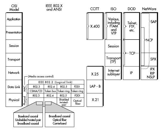
Standards at the physical layer include protocols for transmitting a bit stream over media such as baseband coaxial cable, unshielded twisted-pair wiring, and optical fiber cable. The most commonly used are those specified in the Institute of Electrical and Electronic Engineers (IEEE) 802.3, 802.4, and 802.5 standards and the American National Standards Institute (ANSI) Fiber Distributed Data Interface (FDDI) standard. Figure 11 shows the transmission media included in each of these standards. An emerging standard for this layer is the Synchronous Optical Network (SONET).
The most commonly used layer-two protocols are those specified in the IEEE's 802.2, 802.3, 802.4, and 802.5 standards and the ANSI FDDI standard. Almost all microcomputer networking products use one of these standards (or the virtually identical ISO version) at layer two. Important technologies at this layer include 100Base-T, 100VG-AnyLAN, frame relay, and Asynchronous Transfer Mode (ATM). Layer-two standards encompass two sublayers: media access control and logical link control.
The media access control (MAC) protocol specifies how workstations cooperatively share the transmission medium.
The IEEE 802.3 standard specifies a medium-access method known as "carrier sense multiple access with collision detection (CSMA/CD)." This medium-access method is the same as the contention method described earlier under the heading "The Bus Topology."
The IEEE 802.4, 802.5, and FDDI standards all specify some form of token passing as the media access control method. The basics of the token-passing method were also described earlier, under the heading "The Ring Topology."
In general, using a form of token passing for the media access control works best when large numbers of computers frequently send small amounts of data--for example, when a number of workstations continually read and write small records to and from a database. Contention schemes work well when computers send large amounts of data intermittently--for example, during desktop publishing or document imaging.
The function of the logical link control layer is to ensure the reliability of the physical connection.
The IEEE 802.2 standard is the most commonly used logical link control standard.
The Point-to-Point Protocol (PPP) is an important standard at this OSI level. PPP is used for communications across point-to-point links such as T1 and T3 lines. It is an important protocol for wide area networking, which will be covered later.
The function of the network layer is to manage communications, most importantly the routing and relaying of data, between workstations.
One important network-layer standard is the Department of Defense (DOD) Internet Protocol (IP) specification, which is part of the Transmission Control Protocol/Internet Protocol (TCP/IP) standard developed by the DOD. This protocol is important for two reasons: (1) In most cases, the Department of Defense will not purchase networking products that cannot communicate using this protocol, and (2) The protocol is becoming increasingly popular with all users of network computing, including private businesses and institutions of higher education.
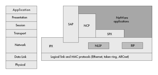
Because Novell commands a large share of the networking market, its native network-layer protocol, Internetwork Packet Exchange™ (IPX™), is also an important network-layer standard. IPX is a connectionless datagram protocol. A connectionless protocol does not need to establish a connection between two networked computers to transfer information between them. Packet acknowledgment, or connection control, is provided by protocols above IPX, such as Novell's Sequenced Packet Exchange™ (SPX™) (SPX will be explained in more detail in a later section). Also, because IPX is a datagram protocol, each communication packet is treated as an individual entity. IPX does not have to establish a logical or sequential relation between packets. Thus, because it is a connectionless datagram protocol, IPX is very efficient--it addresses and transfers data with minimum control overhead.
IPX uses other NetWare protocols that work at the network layer to accomplish internetwork routing. These protocols, the Routing Information Protocol (RIP), the Service Advertising Protocol (SAP), and the NetWare Link Services Protocol™ (NLSP™), will be explained in more detail in a later section.
The Consultative Committee for International Telegraph and Telephone (CCITT) X.25 standard is another commonly used network-layer standard. It specifies the interface for connecting computers on different networks by means of an intermediate connection made through a packet-switched network (for example, a common carrier network such as CompuServe, Tymnet, or Telnet). The X.25 standard includes the data-link and physical-layer protocols shown below it in Figure 11.
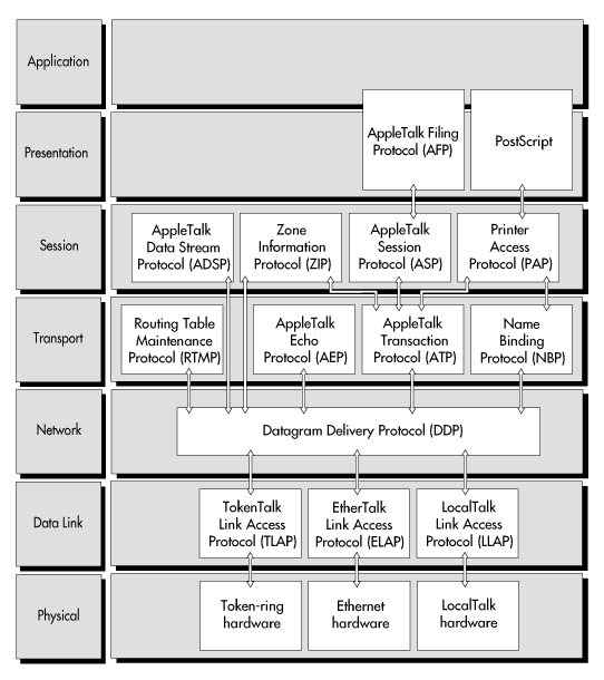
Apple Computer, Inc. has established a set of protocols for its products, referred to collectively as AppleTalk. At the network layer of the OSI model, the Apple protocol is called Datagram Delivery Protocol. Figure 12 shows how the set of AppleTalk protocols fits within the OSI model.
Figure 12: Where AppleTalk protocols fit in the OSI model
Like Novell's native protocols, Apple's standard protocols are important because of Apple's wide acceptance in the microcomputer market.
Standards at this OSI layer provide for the reliability of the end-to-end communication link. This layer isolates the upper three layers, which are all concerned with user and application requirements, from knowing the details required to manage the end-to-end connection.
The ISO has issued a transport-layer standard that is simply called the Transport Protocol (TP). Because it is an ISO standard, it is of worldwide importance.
At the transport layer, Novell's native protocol is SPX. SPX provides guaranteed packet delivery and packet sequencing. Although it is basically a transport-layer protocol, it also includes session-layer functions. The NetWare Core Protocol™ (NCP™) and SAP also provide transport-layer functions. SPX, NCP, and SAP will be treated in more detail in a later section.
The AppleTalk protocol set has a number of protocols that operate at the transport layer, including Routing Table Maintenance Protocol, AppleTalk Echo Protocol, AppleTalk Transaction Protocol, and the Name Binding Protocol.
IBM's NetBIOS protocol (not shown in Figure 11) is also an important protocol at this layer and at the session layer above.
The DOD's Transmission Control Protocol, which is part of the TCP/IP standard, is important at the transport layer in the same degree and for the same reasons as the IP standard at layer three. This protocol provides all functions required for this layer (transport) and part of the functions for the session layer above.
The function of the session layer is to establish, manage, and terminate the connections of individual network users.
The ISO session standard, named simply "session," has the same worldwide importance as the ISO transport standard. The DOD's Transmission Control Protocol, the importance of which was stated previously, performs important functions at this layer.
In a NetWare environment, the NetWare Core Protocol provides most of the necessary session-layer functions. SAP also provides functions at this layer.
The presentation layer performs general data transformations useful to a variety of applications, thus providing a useful common interface. Presentation-layer services include data encryption and text compression. The application layer provides user applications with basic (yet complete) services such as file transfer and network management functions.
Two important OSI protocols encompassing both the presentation and application layers are File Transfer, Access, and Management (FTAM) and Virtual Terminal Protocol (VTP). Each of these protocols is exactly what its name implies. FTAM provides user applications with useful file transfer and management functions. VTP supports applications by converting specific terminal characteristics to a general (virtual) terminal model shared by applications.
X.400 is an important CCITT standard that encompasses both the presentation and application layers. X.400 provides message handling and E-mail services. It is an important standard because it is the basis for a number of pervasive E-mail packages as well as for other widely used messaging products.
An important DOD standard at this level is File Transfer Protocol, which, again, is named for the service it provides.
The NetWare protocols that provide presentation- and application-layer functions are NCP and SAP. All NetWare protocols will be treated in more detail in a later section.
You probably noticed from looking at Figures 11 and 12 that most accepted standards are not neatly packaged to include all (and only) those services specified for any OSI layer. In fact, most common standards encompass parts of multiple OSI layers. This includes most standards adopted by the various government agencies that develop them.
Product vendors' actual implementation of OSI layers is even less neatly divided. Vendors implement accepted standards, which already include mixed services from multiple layers, in different ways.
So why go to all the trouble to agree on a model and then define standards if you are not going to be exact when fitting the standards to the model or in implementing the standards when building a product?
Actually, standards development and implementation have proceeded more or less as expected. The OSI model was never intended to foster a rigid, unbreakable set of rules. It was expected that in implementing the OSI communication model, networking vendors would be free to use whichever standard for each layer they deemed most appropriate. They would also be free to implement each standard in the manner best suited for the purposes of their products.
As noted earlier, however, it is clearly in a vendor's best interest to manufacture products that conform to the intentions behind the OSI model. To do this, a vendor must provide the services required at each OSI model layer in a manner that will enable its system to be simply and easily connected to the systems of other vendors--in other words, vendors must develop open systems. The consequences of not doing so are severe and unavoidable.
Which leads to the next issue--how do you determine if a system is an open system? You can start by getting answers to simple questions such as: (1) Can you establish communications using virtually any accepted communication standard? and (2) How easily can you do this? For example, can you communicate with other networks that are using the TCP/IP protocol, even if your network uses some other protocol at that layer? If you can communicate, what kind of effort is required? And how reliable are such communications?
As you begin asking questions like these, you will find that Novell has the answers you need. NetWare products support every standard we have presented, as well as virtually every other accepted standard. The more you understand NetWare products, the more you will understand that no system is more open than a NetWare system.
From our discussion of the OSI model, you have no doubt begun to understand how complex it is to control communications on a computer network. And, you are probably wondering: What is the means of accomplishing this task? The answer is software called the network operating system.
The network operating system software acts as the command center, enabling all of the network hardware and all other network software to function together as one cohesive, organized system. In other words, the network operating system is the very heart of the network.
On a client-server network, the network operating system (NOS) is installed and runs on a computer called the network server (see Figure 8). The server must be a specific type of computer. For example, the most commonly used client-server version of the NetWare network operating system runs on IBM PC and compatible computers.
A client-server operating system is responsible for coordinating the use of all resources and services available from the server on which it is running.
The client part of a client-server network is any other network device or process that makes requests to use server resources and services. For example, network users at workstations request the use of services and resources though client software, which runs in the workstation and talks to the operating system in the server by means of a common protocol.
On a NetWare client-server network, users "log in" to the network server from the workstation. To log in, a user enters a login command and gives his or her user name and password. If the user name and password are valid, the server logs the user in and allows him or her access to all services and resources to which he or she has been granted rights. As long as the user has proper rights, the client-server operating system provides the services or resources requested by the distributed applications running in workstations.
The operating system manages various server resources, which include hardware such as hard disks, RAM, printers, and equipment used for remote communications, such as modems. The network file system is also a server resource.
In addition, the network operating system provides many services, including coordinating file access and file sharing (including file and record locking), managing server memory, managing data security, scheduling tasks for processing, coordinating printer access, and managing internetwork communications.
Among the most important functions performed by a client-server operating system are ensuring the reliability of data stored on the server and managing server security.
There are many other functions that can and should be performed by a network operating system. We do not have room to cover them all here. However, many functions might be very important to you, and this means that choosing the right NOS is of paramount importance. NetWare NOSs are robust systems that provide many capabilities not found in less mature systems. NetWare NOSs also provide a level of performance and reliability far above that found in most other network operating systems.
To learn more about client-server operating systems, including the services they can and should provide, read the sections that cover the NetWare client-server operating systems, including the NetWare 4.11 NOS [ http://www.novell.com/manuals/bge14110.html ], [ NetWare 4.11 for OS/2 http://www.novell.com/manuals/bge14120.html ], the NetWare 3.12 NOS [ http://www.novell.com/manuals/bge14130.html ], and NetWare 4.11 SFT III [ http://www.novell.com/manuals/bge24110.html ].
Peer-to-peer network operating systems enable networked computers to function as both a server and a workstation. In a peer-to-peer network, the operating system is installed on every networked computer; this enables any networked computer to provide resources and services to all other networked computers. For example, each networked computer can allow other computers to access its files and use connected printers while it is in use as a workstation.
Peer-to-peer operating systems have both advantages and disadvantages when compared to client-server operating systems. They provide many of the same resources and services as do client-server operating systems, and, under the right circumstances, can provide good performance. They are also easy to install and are usually inexpensive.
However, peer-to-peer networks provide fewer services than client-server operating systems. Also, the services they provide are a great deal less robust than those provided by mature, full-featured client-server operating systems, and the performance of peer-to-peer networks commonly decreases significantly under a heavy load. Furthermore, except in the case of Novell's Personal NetWare™ peer-to-peer network operating system, maintenance is often more difficult: Because there is no method of centralized management, there are often many servers to manage (rather than one centralized server), and many people may have access to and the ability to change the configuration of different server computers.
For more information about the differences between peer-to-peer and client-server networks and the level of services they offer, refer to the Personal NetWare product description.
Each workstation on the network must have software that manages its own resources. This software, known as the desktop operating system, enables a workstation to perform such functions as accessing files from its own local hard disks, displaying information on its video display, coordinating local printing, and so on.
There are a number of commonly used desktop operating systems, including Windows, Windows NT, UNIX, PC-DOS, OS/2, MS-DOS, and various versions of the Macintosh operating system.
Each of the different desktop operating systems has advantages and disadvantages. Unfortunately, for the most part, they are not compatible with each other. Software written for one operating system will not function on another. Furthermore, peripheral hardware (such as modems, facsimile machines, and so on) that is compatible with the hardware required to run one kind of desktop operating system is usually not compatible with hardware required to run other desktop operating systems.
This brings us to another important function of a network operating system--it should be able to interconnect all of the commonly used desktop operating systems to ensure that all network users have access to the computer that they are most familiar with and that is best suited to the job they need to do.
Novell network operating systems enable you to integrate all popular desktop operating systems directly on one network. They allow this because they are able to translate the data from one desktop operating system into data that the other desktop operating systems can read.
Once you have your network hardware, a powerful network operating system, and the necessary desktop operating system(s), the final network tool you will need is application software. Application software enables you to do the "real work" you want to do. Commonly used application software includes word processing, accounting, spreadsheet, and database programs. You may also need customized applications, or even one-of-a-kind applications, built specifically for your company.
One extremely important issue to consider when selecting commercially built application software is its degree of network integration. To effectively use network services, application software must be well integrated with the network operating system. The degree of network integration will determine how well the application enables collaboration among network users, whether and how well it provides direct access to all network services, and whether it is as easy as it can be to manage across the network.
As businesses grow, they often need more than one network. In fact, even a modest-sized business often has several networks operating, each serving a specific portion of the organization.
Why might a business need more than one network?
First, even the fastest and most efficient network can become overloaded with more users and data than it can easily handle. By adding another network, you can split the workload and restore responsiveness. Second, confidential information--payroll and human resources information, for example--can be kept more securely if stored on its own network. Third, having several networks helps ensure that a single failure will not bring the entire organization to a halt. You can duplicate on different networks software and data required to continue critical functions. If the primary network fails, you can simply log in to backup networks and continue as before.
Whatever the reason for having more than one network, it often becomes necessary to connect separate networks to share information between them. When two or more networks are connected, the result is called an internetwork; each of the connected networks is a subnetwork.
Internetworking includes everything from connecting two small workgroup networks, each with perhaps two or three workstations, to connecting thousands of computers--from notebook computers to mainframes--on tens to hundreds of individual subnetworks in a worldwide organization.
Bridges and routers are the devices used to interconnect networks. They can be primarily hardware based or primarily software based.
Software-based routers and bridges can be part of a server's operating system or can at least run in the server with the operating system. Software-based bridges and routers can also be installed on standard computers to create dedicated, standalone devices. For example, NetWare MultiProtocol Router™ software is a family of software-based routing products that can be installed on either a NetWare 3™ or NetWare 4™ server or on a standalone PC.
To understand internetworking, it is not essential that you understand all the technical differences between a bridge and router. In fact, without some study, this can be a confusing area. For example, if you read about NetWare MultiProtocol Routers, you will find that these routers also perform what is called source-route bridging.
However, without a basic understanding of bridging and routing technology (and related terminology), you will find it difficult to understand the capabilities of some products and the reasons such capabilities are useful or important. Please keep in mind throughout the following discussion that bridges and routers have one important thing in common: They both allow the transfer of data packets (frames) between networks with different network addresses.
A bridge operates at the data-link layer (layer two) of the OSI model. Bridges can be used to connect networks with different addresses or to segment a network (segments having the same network address). When connecting networks with different addresses, a bridge acts as an address filter; it relays data between networks with different addresses based on information contained at the media access control level.
Simple bridges are used to connect networks that use the same physical-layer protocol and the same MAC and logical link protocols (OSI layers one and two). Simple bridges are not capable of translating between different protocols.
Other types of bridges, such as translational bridges, can connect networks that use different layer-one and MAC-level protocols; they are capable of translating, then relaying, frames.
After a physical connection is made (at OSI layer one), a bridge receives all frames from each of the networks it connects, and it checks the network address of each received frame. The network address is contained in the MAC header. When a bridge receives a frame from one network that is addressed to a workstation on another network, it passes the frame to the intended network. Figure 13 illustrates, in a general fashion, how a bridge relays frames between networks.
Figure 13: Internetworking through a bridge
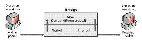
A bridge assumes that all communication protocols used above the data-link layer at which it operates (OSI layers three through seven) are the same on both sides of the communication link. Of course, this must be true, or there must be translation between unlike protocols at layers three through seven for the receiving computer to be able to interpret the transferred data.
There are two terms connected with bridging that will be useful to understand: spanning trees and source-route bridging.
Spanning trees prevent problems resulting from the interconnection of multiple networks by means of parallel transmission paths. In various bridging circumstances, it is possible to have multiple transmission routes between computers on different networks. If multiple transmission routes exist, unless there is an efficient method for specifying only one route, it is possible to have an endless duplication and expansion of routing errors that will saturate the network with useless transmissions, quickly disabling it. Spanning trees are the method used to specify one, and only one, transmission route.
Source-route bridging is a means of determining the path used to transfer data from one workstation to another. Workstations that use source routing participate in route discovery and specify the route to be used for each transmitted packet. Source-route bridges merely carry out the routing instructions placed into each data packet when the packet is assembled by the sending workstation--hence the name "source routing." In discussions of bridging and routing, do not be confused by the term "source routing." Though it includes the term "routing," it is a part of bridging technology. Source-route bridging is important because it is a bridge-routing method used on IBM Token-Ring networks.
You should understand that bridging technologies and routing methods can be combined in various ways. For example, there is an IEEE specification for a source-route transparent bridge, a bridging scheme that merges source-route bridging and transparent bridging in one device.
From this simple discussion of bridging, one thing should be apparent: When picking internetworking products, it is important to select those that support the various bridging methods--products such as NetWare MultiProtocol Routers. (For further details, see the NetWare MultiProtocol Router 3.1 [ http://www.novell.com/manuals/bge34110.html ] section.)
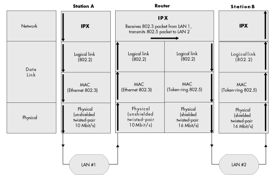
Routers function at the network layer of the OSI model (one layer above bridges). To communicate, routers must use the same network-layer protocol. And, of course, the sending and receiving workstations on different networks must either share identical protocols at all OSI layers above layer three, or there must be necessary protocol translation at these layers.
Like some bridges, routers can allow the transfer of data between networks that use different protocols at OSI layers one and two (the physical layer and the data-link layer, which includes sublayers for media access control and logical link control). Routers can receive, reformat, and retransmit data packets assembled by different layer-one and layer-two protocols. Different routers are built to manage different protocol sets. Figure 14 illustrates how a router transfers data packets.
Figure 14: Internetworking through a router
Before we conclude with a discussion of host connection, wide area networking and technologies, and global networks, you should understand a little more about native NetWare protocols that play a role in NetWare internetworking. Figure 15 shows in greater detail how NetWare protocols fit into the OSI model.
Figure 15: Where NetWare protocols fit in the OSI model
Each of the native NetWare protocols shown in Figure 15 plays a role in NetWare internetworking, either directly or indirectly.
In conjunction with industry-standard media access control protocols, the NetWare IPX protocol provides the NetWare addressing mechanism that delivers communication packets to their destination. IPX works with all important MAC standards. As you can see from Figure 15, IPX operates at the network layer of the OSI model.
In a NetWare environment, internetwork packet routing is accomplished at the network layer. Thus, IPX is the NetWare protocol that addresses and routes packets between internetworked computers.
IPX bases its routing decisions on the address fields in its packet header (provided by the MAC protocol) and on the information it receives from other NetWare protocols. For example, IPX uses information supplied by either RIP or NLSP to forward packets to the destination computer or to the next router. IPX also uses SAP.
NetWare routers use one of two routing protocols, RIP or NLSP, to exchange routing information with neighboring routers.
The NetWare RIP is a distance-vector protocol. Distance-vector routing protocols are the traditional method used for router communications.
In an internetwork using distance-vector routing, routers periodically determine if the internetwork configuration has changed. They also periodically broadcast packets to their immediate neighbors; these packets contain all information they currently have about the internetwork's topology.
After receiving any information, distance-vector routers consolidate the information and pass summarized data along to other routers, servers, and end devices, such as printers and workstations. Through this periodic checking and broadcasting, which is performed at regular intervals regardless of whether the internetwork has changed, all routers are kept updated with correct internetwork addresses for all computers and other connected devices, as well as with the best route for transferring data between any two devices.
Because RIP is a distance-vector protocol, NetWare routers that use RIP work in the way described above, performing periodic checking and information exchange and updating their routing tables with any new information.
RIP is one of a number of well-known distance-vector routing protocols. Examples of other such protocols include IP RIP and Cisco IGRP, part of the IP protocol suite, and RTMP, part of the AppleTalk protocol suite.
The NetWare Link Services Protocol is a link-state routing protocol. This type of protocol derives its name from the fact that link-state routers track the status of other routers and links.
Link-state protocols, a relatively recent development, adapt more quickly to network topology changes than do distance-vector protocols. Thus, they are better than distance-vector protocols for managing internetworking on large, complex internetworks.
In an internetwork that uses a link-state routing protocol, each router or server provides information about itself and its immediate neighbors to every reachable router in a routing area. Each router's map includes all the area's routers and servers, the links connecting them, and the operational status of each router and link. However, each router builds its own routing map rather than relying on secondhand summaries, as do distance-vector routers. Also, routing transmissions are made only when the internetwork changes, not at predefined intervals, regardless of whether the internetwork has changed. Thus, networks using link-state routing are not burdened by unnecessary routing traffic.
Because NLSP works as explained above, it significantly reduces the communication overhead required for routing. NLSP can significantly improve network performance because it frees resources to be used for transferring data packets rather than routing information. NLSP is particularly efficient for wide area network routing, where available communication bandwidth is ordinarily limited.
Examples of other link-state protocols include the Open Shortest Path First protocol, part of the TCP/IP protocol suite, and the Intermediate System-to-Intermediate System protocol, a router-to-router protocol that is part of the OSI suite.
As a matter of note, various link-state and distance-vector routing protocols can coexist on the same NetWare internetwork and even in the same NetWare MultiProtocol Router. Furthermore, individual routers can be configured to accept or to reject individual protocols.
The Service Advertising Protocol is similar in concept to RIP. Just as RIP enables routers to exchange routing information, SAP enables networked devices, such as network servers and routers, to exchange information about available network services.
Servers and routers use SAP to advertise their services and network addresses. SAP enables network devices to constantly correct their information about which network services are available. While servers are running, they use SAP to inform the rest of the network of the services they offer. When a server goes down, it uses SAP to inform the network that its services are no longer available.
Routers gather service information and share it with other routers. Workstations use the information made available through SAP to obtain the network addresses of servers that offer the services they need.
The NetWare Core Protocol is a set of service protocols that a server's operating system follows to accept and respond to service requests.
NCP does not play a direct role in routing. However, it does provide session control and packet-level error checking between NetWare workstations and routers.
SPX is a transport-layer protocol. Standards at this OSI layer provide for the reliability of the end-to-end communication link. Accordingly, SPX provides guaranteed packet delivery and packet sequencing.
Like NCP, SPX does not play a direct role in routing. SPX is connected with internetworking only in that it guarantees delivery of all routed packets.
In contrast to bridges and routers, which function at only one layer of the OSI model, a gateway translates protocols at more than one OSI layer. Therefore, a gateway is used to interconnect computer systems that have different architectures and that therefore use different communication protocols at several OSI layers.
A gateway may connect dissimilar systems on the same network or on different networks (thus, using a gateway does not necessarily involve internetworking). For example, a gateway might translate protocols at several different OSI layers to allow transparent communications between NetWare IPX-based systems and systems based on TCP/IP, System Network Architecture (SNA), or AppleTalk. Figure 16 illustrates how a gateway is used to translate protocols to enable communications between two heterogenous systems.
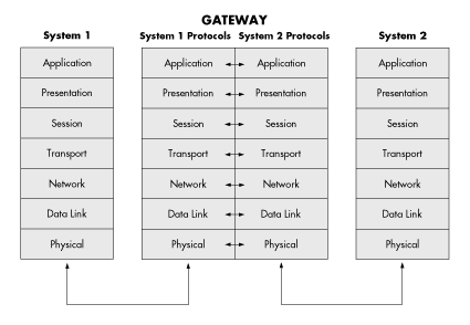
A gateway may consist of hardware, software, or a combination of the two, and it may provide translation at all or at only some of the different OSI layers, depending on the types of systems it connects.
There are a number of NetWare gateways that provide access to computer systems not based on the native NetWare/IPX protocol suite. NetWare for Macintosh is a software-based gateway that connects Macintosh computers to a PC-server-based NetWare network. NetWare for SAA is a gateway that enables NetWare users to transparently access SNA-based IBM hosts, and NetWare for DEC Access is a gateway that enables transparent access to Digital Equipment Corporation (DEC) hosts.
In the real world, computer networks can take an almost unlimited number of physical and topological forms. We've already seen a very simple network. Now let's take a look at more complex networks. We'll start with simple internetworks and work our way gradually through more complex situations. For the sake of simplicity and clarity, all of the subnetworks in our internetworks will be based on the NetWare client-server networking model.
The simplest form of an internetwork is two cabling systems of the same media access control type sharing one network server.
For example, one server could contain two Ethernet network adapters, each supporting a different cabling system. There could be several computers connected to each cabling system, in a star physical layout, with each cabling system using contention (CSMA/CD) for the media access control. Each of the cabling systems would have a different network address--thus, each would be an independent network.
Together, the two separate networks would form an internetwork, connected by means of internal routing capabilities built into the server. (Remember, we have already said that in NetWare servers, internetworking is accomplished through routing at the network layer.)
Figure 17 illustrates the one-server internetwork described above.
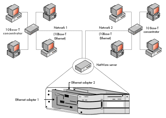
In the case of the above network, routing would be accomplished using the NetWare IPX protocol, with support from the other NetWare routing protocols, as previously described.
Every NetWare server is capable of using internal routers to accomplish local network routing by means of the NetWare routing protocol set, as well as by IP and AppleTalk. All NetWare internal routers operate at layer three of the OSI model and are for use with small workgroup or departmental networks. For larger or more complicated internetworks, or for departments with heavy server-processing requirements, the NetWare MultiProtocol Routers provide the necessary extra routing power and capabilities.
In a slightly more complex internetwork, a NetWare server could support cabling systems using the same physical layouts but different media access controls.
For example, a server could contain one Ethernet network adapter and one token-ring network adapter, with a cabling system attached to each. The Ethernet network might be connected in a physical star and use CSMA/CD for the media access control. The token-ring network might also be connected in a physical star, but it would use token passing for media access control. Like the simpler configuration explained above, each cabling system would have a different network address. Figure 18 illustrates this more complex one-server internetwork.
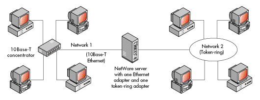
In the case of the internetwork shown above, routing would again be accomplished using the NetWare IPX protocol, with support from the other NetWare routing protocols.
The two one-server networks we have seen each support only two separate networks. As a matter of note, all NetWare servers are capable of supporting as many as four different network adapters (four separate networks), in any combination of same or different types.
Please notice that even though the token-ring network above was described as a physical star, it is drawn as a ring to signify that it is a token-ring network (which uses token passing as the media access control). We will adhere to this convention throughout this primer because in virtually all illustrations it will be more important to make the topology clear than to be concerned with the actual physical layout.
In an even more complex internetwork, there may be multiple servers.
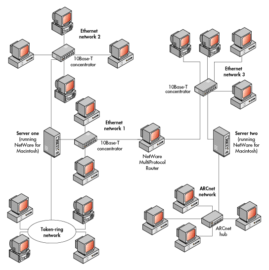
For example, a complex internetwork might consist of two one-server internetworks connected by a standalone router, such as the NetWare MultiProtocol Router, to form a larger two-server internetwork. Each server might contain multiple network interface adapters.
One server might contain two Ethernet network adapters and one token-ring network adapter, with a cabling system attached to each. One of the Ethernet adapters might support a PC network, and the other Ethernet adapter might connect to both PCs and Macintosh computers. The NetWare for Macintosh product running on the server would support the Macintosh computers.
The other server might contain one Ethernet adapter and one ARCnet adapter, with the Ethernet adapter again supporting both PCs and Macintoshes, and the ARCnet adapter supporting a cabling system with a number of PCs attached.
Each of the two servers would have a unique internal network number (address), and each cabling system in each server would have a unique physical network address.
In this case, there would be five subnetworks on the internetwork, three attached to one server and two attached to the other. The internal server routers would accomplish the routing between any two workstations on networks attached directly to the same server. The intermediate standalone router would accomplish the routing between any two workstations on networks attached to different servers.
Figure 19 illustrates the two-server internetwork described above.
An already complex multiserver internetwork becomes even more complex with the addition of connections to host computer systems, including mainframe computers such as IBM mainframes, to minicomputers such as IBM's AS/400 or a DEC VAX system, or to other hosts such as UNIX workstations.
Host systems can provide access to additional application software, additional resources such as data storage devices and printers, and additional processing power. For example, you might want to log in to an IBM AS/400 minicomputer to run an application available only on that computer or to use its processing power for one task while you were using the processing power of your own workstation for some other task. Or, you might want to print a large report on a high-speed printer connected to the AS/400.
The illustration in Figure 20 shows a multiserver NetWare network with an IBM mainframe, an IBM AS/400 minicomputer, and several UNIX workstations connected as host computers.
Figure 20: Host systems connected to a complex multiserver NetWare network
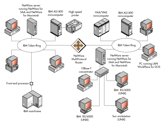
A number of leading networking companies have entered into original equipment manufacturer (OEM) partnerships with Novell. Many provide NetWare connectivity to host-based environments.
So far, we have looked only at internetworks existing at one local site, with computers and other devices directly connected by some type of cabling. This type of network is commonly referred to as a "local area network" (LAN). Now let's add another level of complexity to the internetworking picture: Let's connect complex multiserver internetworks that exist at separate sites, which might be any number of miles apart. Connecting computer networks in these circumstances is called "wide area networking."
The traditional definition of wide area networking has been "connecting two or more networks existing at widely separate geographic sites." Some traditionalists also prescribe that the separate networks must be connected by means of common carrier telecommunication facilities (private companies that rent resources such as T1 lines and microwave transmission equipment). For the purposes of this primer, we'll use the first, most general definition and let you decide how to apply it in specific internetworking cases. But, to give you some background to help you make such decisions, let's discuss a few specific internetworking cases and a few terms related to wide area networking.
Of course, like any general term used in connection with rapidly changing technology, not everyone will agree on an exact definition of wide area networking. What is "widely separate"? And, does the connection really have to be through a common carrier? Many major companies now own their own equipment linking networks many miles apart.
Let's look at some examples. Suppose you connect two networks in two different buildings 100 yards apart by means of asynchronous modems and common telephone lines. Is that wide area networking? Most knowledgeable computer networking people would say no--this would be "one-site" or "campus" networking. What if the networks were two miles apart and separated by a major interstate highway? Or, what if they were 15 miles apart, on opposite sides of a major city? There are many computer networking people who would still not call this wide area networking; they might use a recently coined term--"metropolitan area networking." Others consider metropolitan area networking a part of wide area networking. Of course, almost everyone agrees that two networks connected on opposite sides of a continent by means of a satellite microwave link rented from a common carrier is an example of a wide area network.
You can decide for yourself where you think wide area networking begins and ends. Now let's look at some general possibilities.
Figure 21 shows two separate branch office internetworks connected to a third internetwork at a main corporate office. Each of the three existing internetworks has multiple servers and existing host connections. One of the branch office networks is connected to the corporate network by means of asynchronous modems and regular voice-grade telephone lines. The other branch office network is connected by means of a common carrier-provided intermediate link--in this case an X.25 packet-switching network. Examples of such networks include Tymnet or Telenet.
However, either network could be connected by other means that we have discussed, such as a microwave link or leased lines, perhaps using PPP.
The following section describes important WAN and LAN technologies in greater detail.
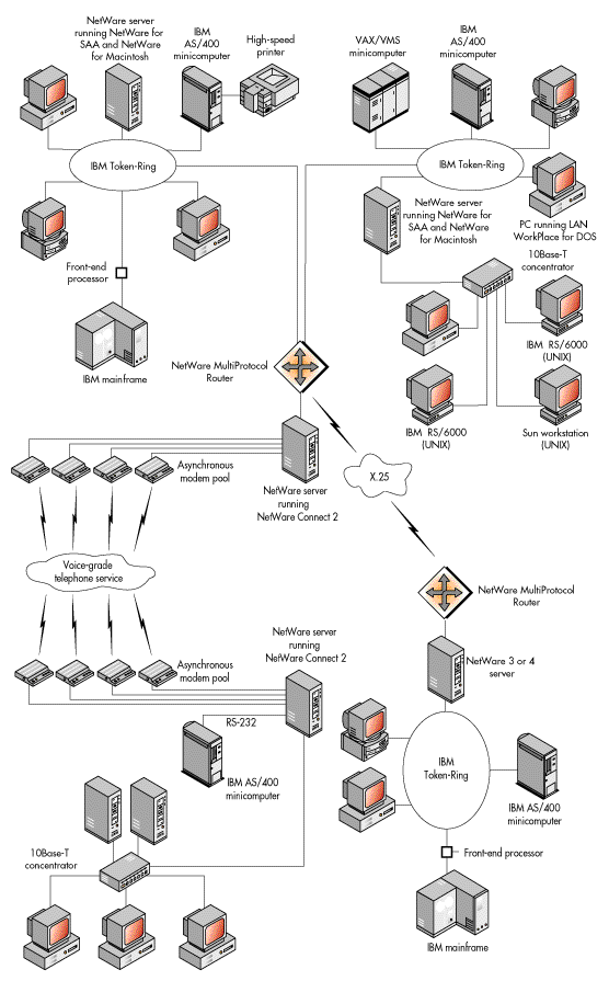
These days, if you pick up any computer networking magazine, you'll find that among the hot topics are the technologies that make networks faster and connect geographically distant networks--technologies such as frame relay, 100VG-AnyLAN, and ATM. We mentioned these and other high-speed and WAN technologies under the "Commonly Used Standards" heading of this primer. Brief explanations will help you more fully understand what these technologies are and why they are important. The following technologies will be treated:
100Base-T is a high-speed LAN technology. 100Base-T is officially designated as the IEEE 802.3u standard. It functions at the data-link (OSI level two) layer's medium access control sublayer and provides data transfer rates as high as 100 megabits per second (Mbit/s).
Like 10Base-T Ethernet, 100Base-T uses carrier sense multiple access with collision detection as the medium access control method. (CSMA/CD was discussed earlier under the "Bus Topology" heading of this primer.) 100Base-T is based on the scalability of CSMA/CD. Scalability is the ability of something to be made larger or smaller. It usually implies a minimum effort to accommodate growth or reduction.
CSMA/CD was known to be scalable before the 100Base-T standard was created. A scaled-down version of Ethernet (1Base-5) uses CSMA/CD, provides data transfer rates of 1 Mbit/s, and enables longer transmission distances between repeaters. If CSMA/CD could be scaled down, then it could be scaled up. Specifying changes such as decreased transmission distances between repeaters produced a reliable data transfer rate for 100Base-T Ethernet of 100 Mbit/s, 10 times faster than traditional 10Base-T Ethernet.
100Base-T supports Category 3 and 5 unshielded twisted-pair (UTP) wiring, Type-1 shielded twisted-pair (STP) wiring, and fiber-optic cable. It uses four wire pairs of Category 3 UTP cable--three for data and one for collision detection. However, 100Base-T uses only two wire pairs of Category 5 UTP cable.
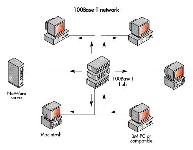
100Base-T is widely available. Adapter cards and cable to install or upgrade to 100Base-T are currently available from various vendors.
In addition, it's easy to upgrade from 10Base-T Ethernet to 100Base-T Ethernet. Both traditional 10Base-T and 100Base-T Ethernet use CSMA/CD, and some network cards now support both 10 Mbit/s and 100 Mbit/s Ethernet. The adapter cards automatically sense whether it is a 10 Mbit/s or 100 Mbit/s environment and adjust accordingly. Therefore, 100Base-T and traditional 10Base-T Ethernet can exist on the same network, enabling network supervisors to upgrade at their own pace. Also, CSMA/CD is already familiar to many network supervisors, minimizing the need for retraining.
Moreover, 100Base-T can be an inexpensive way to make your network faster. Network adapter cards for 100Base-T are only about twice the price of 10Base-T Ethernet cards. In addition, Category 3 and Category 5 UTP cable are relatively inexpensive and many organizations already have either Category 3 or 5 cable installed.
100Base-T will reduce the maximum network size compared to 10Base-T because the standard specifies shorter transmission distances between repeaters.
In addition, the fact that 100Base-T is based on CSMA/CD creates problems. 100Base-T may scale CSMA/CD to its limit, making 100 Mbit/s the maximum data transfer rate for this standard. To increase data transfer rates, 100Base-T specifies shorter distances between signal repeaters, but these distances may be as short as is practical. Also, because CSMA/CD is a contention scheme, collisions will occur, especially under maximum loads, reducing network throughput.
Furthermore, 100Base-T requires four wire pairs of Category 3 cable, but not all companies have four wire pairs available. Thus, companies that are already using some wire pairs for a different purpose, or that installed cable with less than four wire pairs or that does not meet Category 3 standards, will have to recable to use 100Base-T.
100VG-AnyLAN, which is officially designated as the IEEE 802.12 standard, is a high-speed LAN technology that competes with 100Base-T. Like 100Base-T, 100VG-AnyLAN functions at the data-link layer (OSI level two) and provides data transfer rates as high as 100 Mbit/s. However, 100VG-AnyLAN differs from 100Base-T in several important respects.
Instead of using CSMA/CD as the medium access control method, 100VG-AnyLAN uses a method called demand priority. Demand priority is not a contention scheme; rather, it uses a form of token passing that assigns the token (permission to broadcast data packets) based on a priority scheme that the network supervisor establishes for different types of LAN traffic and on the order in which an intelligent hub receives requests.
For example, when a workstation needs to transmit, it signals the intelligent hub that it needs access to the transmission media. If the intelligent hub receives several requests, it will give access to the workstation that has the highest priority. (100VG-AnyLAN will also function without a prioritization scheme.) If the workstations requesting access have the same priority, the intelligent hub will assign the token to the workstations in the order they request access to the transmission media.
In addition, 100VG-AnyLAN supports both Ethernet and token-ring networks. It also supports Category 3 and 5 UTP, Type-1 STP, and fiber-optic cable. 100VG-AnyLAN uses four wire pairs of Category 3 or Category 5 UTP cable.
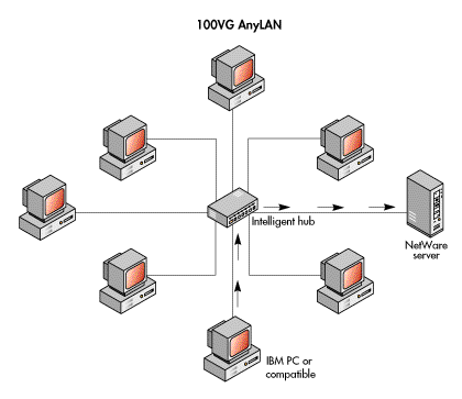
Because 100VG-AnyLAN uses demand priority, it has several advantages over 100Base-T. First, 100VG-AnyLAN provides the necessary bandwidth and timing (low latency) needed by applications such as multimedia applications. Network supervisors can, if desired, assign higher priority to the hub ports used to connect workstations or servers that frequently transmit time-sensitive data, such as audio and video. Second, the demand priority media access method avoids the collisions that can occur on 100Base-T networks. Third, 100VG-AnyLAN networks do not broadcast packets to all workstations, which makes 100VG-AnyLAN networks more secure against eavesdroppers than 100Base-T networks.
Furthermore, unlike 100Base-T, 100VG-AnyLAN supports token-ring networks as well as Ethernet, providing data transfer rates as high as 100 Mbit/s to the former.
100VG-AnyLAN and 100Base-T also share many advantages. The cost of 100VG-AnyLAN is comparable to 100Base-T: Adapter cards that support both 10 and 100 Mbit/s are about twice the price of traditional 10Base-T Ethernet cards. Both standards also support the same types of transmission media. In addition, both offer an easy upgrade.
Unlike 100Base-T's CSMA/CD, which is familiar to many network supervisors, demand priority is new, and network supervisors will require some training to use it effectively. Also, 100VG-AnyLAN has a smaller market share than 100Base-T. Consequently, it is not supported by as many vendors, which means that fewer products are available for 100VG-AnyLAN.
Previously installed cable may be problematic for 100VG-AnyLAN networks, as it is for 100Base-T. 100VG-AnyLAN uses all four wire pairs of Category 3 or 5 UTP cable. Thus, companies that are already using some wire pairs for a different purpose, or that installed cable with less than four wire pairs or that does not meet Category 3 standards, will have to recable to use 100VG-AnyLAN.
Fiber Distributed Data Interface is also a high-speed LAN technology. It is not generally used for direct connection to desktop computers, but rather as a backbone technology. A backbone connects two or more LAN segments to provide a path for transmitting packets among them. A simple backbone might connect two servers through a high-speed link consisting of network adapter cards and cable.
FDDI is officially designated as ANSI X3T9.5 and operates at the physical and data-link layers (levels one and two) of the OSI model. Like 100Base-T and 100VG-AnyLAN, FDDI provides data transfer rates as high as 100 Mbit/s.
Figure 24: A simple server-based backbone connecting two LAN segments
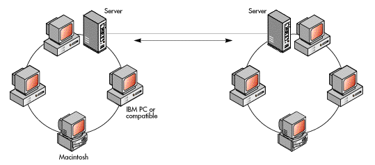
FDDI networks have a dual, counter-rotating ring topology. This topology consists of two logical closed signal paths called rings. Signals on the rings travel in opposite directions from each other. Although both rings can carry data, the primary ring usually carries data while the secondary ring serves as a backup.
On FDDI networks, every node acts as a repeater. FDDI supports four kinds of nodes: dual-attached stations (DASs), single-attached stations (SASs), single-attached concentrators (SACs), and dual-attached concentrators (DACs). DASs and DACs attach to both rings; SASs and SACs attach only to the primary ring. Several SASs often attach to the primary ring through a concentrator so that an SAS failure will not bring down the entire network. If the cable is cut or a link between nodes fails, DASs or DACs on either side of the failure route signals around the failed segment using the secondary ring to keep the network functioning.
FDDI uses token passing for the medium access control method and is implemented using fiber-optic cable.
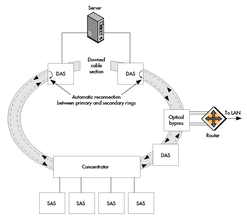
FDDI is a fast, reliable standard. The dual, counter-rotating ring topology increases the network's reliability by keeping the network functioning even if a cable is damaged. FDDI also offers network management support, which was designed directly into the standard. Also, the standard includes a specification for UTP cable called Copper Distributed Data Interface (CDDI), which is less expensive than fiber-optic cable.
FDDI's main disadvantage is price. FDDI adapter cards and fiber-optic cable are both relatively expensive compared to other technologies offering the same speed. Fiber-optic cable installation also requires more expert technicians. Even CDDI adapters, which are less expensive than FDDI adapters, are more expensive than either 100Base-T or 100VG-AnyLAN adapters.
X.25 is a commonly used WAN standard at the network layer (level three) of the OSI model. It is a CCITT (now known as the International Telecommunications Union (ITU)) standard and includes data-link and physical layer protocols (LAP-B and X.21), as shown in Figure 11. X.25 provides data transfer rates of 9.6 kilobits per second (Kbits/s) to 256 Kbits/s, depending on the connection method.
X.25 specifies the interface for connecting computers on different networks by means of an intermediate connection through a packet-switched network (for example, CompuServe, Tymnet, or Telnet). X.25 was defined when the quality of transmission media was relatively poor. As a result, the standard specifies that each node in the packet-switched network must fully receive each packet and check it for errors before forwarding it.
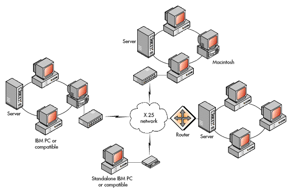
X.25 is well understood and reliable. Connections to X.25 networks can be made through the existing telephone system, ISDN, and leased lines. Because access is so simple, it is comparatively inexpensive. X.25 is also available worldwide. In countries with little or no digital telecommunications infrastructure, X.25 may be the best WAN technology available.
Although it is widely available, X.25 is slow compared to newer technologies. The process of checking each packet for errors at each node limits data transfer rates. It also uses variable-size packets, which can cause transmission delays at intermediate nodes. In addition, many people connect to X.25 networks through modems, which limit data transfer rates to 9.6 Kbit/s to 28.8 Kbit/s. Although X.25 is likely to remain in use for some time, newer, faster standards are already replacing it.
Frame relay, like X.25, is a WAN technology. Approved by ANSI and the ITU, frame relay works at the data-link layer (level two) of the OSI model, providing data transfer rates from 56 Kbits/s to 1.544 Mbits/s.
Frame relay is an interface specification for connecting LANs over public packet-switched networks. This standard can be thought of as a simplified version of X.25 designed to take advantage of digital transmission media.
Frame relay services are typically provided by telecommunications carriers. Customers install a router and lease a line (often a T1 or fractional T1 line) to provide a permanent connection from the customer's site to the telecommunications carrier's network. This connection enables frame relay to use permanent virtual circuits (PVCs), which are predefined network paths between two locations.
With frame relay, the router encapsulates (or frames) network layer packets, such as IP and IPX packets, directly into a data-link level protocol and sends them on to the packet-switched network. Like X.25, frame relay uses variable-size frames, but it eliminates the error checking required on X.25 networks. A frame relay switch simply reads the header and forwards the packet, perhaps without even fully receiving a frame before forwarding it. Intelligent end stations must identify missing or corrupted frames and request retransmission.
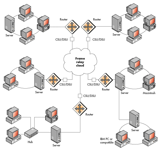
Frame relay offers several advantages over X.25. Most importantly, frame relay is faster than X.25. Frame relay uses PVCs over leased lines rather than a modem connection. Unlike modem connections, PVCs transmit and receive data immediately, eliminating the call setup and handshaking that modems must perform. In addition, as mentioned above, frame relay does not require error checking and flow control at the switches, reducing overhead and leaving more bandwidth for data transmission. Also, although not as prevalent as X.25, frame relay is a common standard in many countries. Finally, frame relay is less expensive than other WAN technologies because it provides bandwidth on demand, rather than dedicating bandwidth whether data is being transmitted or not.
Although frame relay is faster than X.25, its speed is limited because it uses variable-size frames, which can cause delays at switches along the frame's path. As a result, frame relay cannot support applications that require low latency, such as real-time video.
In addition, frame relay is more complex to implement than X.25. Customers must negotiate a service agreement with the phone company, lease a line, and have it installed. They must also purchase and install a frame relay-compatible router. Value-added resellers and some telephone companies will assist customers in determining their needs and will help install the technology.
Asynchronous Transfer Mode is both a LAN and a WAN technology. It is generally implemented as a backbone technology. In the OSI model, ATM works at the data-link layer (level two).
ATM is extremely scalable; data transfer rates range from 25 Mbit/s to 2.4 gigabits per second (Gbit/s). This wide range of data transfer rates reflects the various ways in which ATM can be used. The 25 Mbit/s rate is a new offering meant for desktop environments. In LAN backbones, ATM provides data transfer rates of 100 Mbit/s and 155 Mbit/s. At the high end, WAN implementations using ATM and SONET together have achieved data transfer rates of 2.4 Gbit/s. (To learn more about SONET, see the "Synchronous Optical Network" section in this primer.)
ATM is a cell relay technology, meaning that it uses standard-sized packets called cells. The size of an ATM cell is 53 bytes.
In a LAN implementation, ATM functions at the data-link layer's medium access control sublayer. It further divides the MAC sublayer into three layers: LAN Emulation, ATM Adaptation Layer (AAL), and ATM. LAN Emulation enables you to integrate ATM with Ethernet and token-ring networks without modifying existing Ethernet or token-ring protocols.
On a mixed network, LAN Emulation hardware sits between the Ethernet or token-ring segment and the ATM part of the network. It uses the three layers mentioned above to convert packets moving toward the ATM segment into cells and to assemble cells moving toward the Ethernet or token-ring segment into packets. AAL and ATM put data into standard-sized cells. In most network computing situations, ATM Adaptation Layer 5 breaks packets into 48-byte blocks that are then passed to the ATM layer, where the five-byte header is attached to form a complete 53-byte cell.
Many people believe that ATM will become the industry-standard transmission technology for LANs and WANs. The scalability, discussed above, seems to be limitless. Data transfer rates have climbed into the gigabit range and are still growing.
One reason that ATM is so fast is its use of cells. Because cells are a standard size, ATM networks handle data in a predictable, efficient manner at the switches. Standard-sized cells and high-bandwidth media like fiber-optic cable also enable ATM to support real-time voice, video, and data traffic.
ATM also offers flexibility in its transmission media. As many as 22 ATM specifications exist for media like unshielded twisted-pair, shielded twisted-pair, and fiber-optic cable. (ATM is generally implemented with fiber-optic cable.)
Although it is seen as a technology of the future, ATM can presently work with Ethernet and token-ring networks using LAN Emulation.
ATM standards are still developing. Without industry standards, interoperability between equipment from different vendors is not guaranteed. Furthermore, ATM is more expensive than the other high-speed LAN technologies. The expense is preventing many companies from taking ATM to the desktop.
Integrated Services Digital Network is a set of protocols defined by CCITT to integrate data, voice, and video signals into digital telephone lines. It functions at the physical, data-link, network, and transport layers (levels one through four) of the OSI model. ISDN offers data transfer rates between 128 Kbit/s and either 1.544 Mbit/s or 2.048 Mbit/s, depending on what country you live in.
ISDN makes end-to-end digital connections over telephone lines. Although many telephone networks are almost completely digital, the local loop that connects a home or office to the telephone company's network is not: Most local loops send analog rather than digital signals. ISDN replaces local analog signaling with end-to-end digital, enabling digital communications.
ISDN offers Basic Rate Interface (BRI) for individuals or small branch offices and Primary Rate Interface (PRI) for larger companies. BRI uses two bearer, or B, channels (providing 64 Kbit/s each) to transmit and receive data and one delta, or D, channel for call setup and management.
PRI is also called a T1 line. A T1 line in the United States consists of 23 B channels and one D channel, providing a total data transfer rate of 1.544 Mbit/s. A T1 line in Europe consists of 30 B channels and one D channel, providing a total data transfer rate of 2.048 Mbit/s. A fractional T1 uses only some of the B channels in a T1 line (and thus offers some fraction of the total T1 data transfer rate).
ISDN requires special equipment at the customer's site, including a digital phone line and a network termination unit (NT-1). An NT-1 converts the bandwidth coming over the line into the B and D channels and helps the phone company with diagnostic testing. The NT-1 also provides a connection for terminal equipment, such as ISDN telephones and computers that have an ISDN interface. In addition, the NT-1 provides terminal adapter (TA) equipment to connect equipment that is not compatible with ISDN. TA equipment has an ISDN interface on one side and a non-ISDN interface on the other.
ISDN increases speed and broadens data transmission capabilities, especially for those currently using analog modems to remotely connect to an office or to access the Internet. It offers faster call setup and faster data transfer rates, which enable ISDN to transmit voice, data, limited video, fax, and images. ISDN can also be used for limited LAN-to-LAN communications.
ISDN offers the flexibility to transmit voice and data traffic simultaneously. An ISDN user could download information and talk on the phone at the same time. For example, one configuration enables BRI ISDN users to use the two B channels (128 Kbit/s) for data and part of the D channel for a phone conversation.
Although widely available in Australia, Japan, and Western Europe, ISDN is available in only 50 percent of the United States. Presently, telephone companies are working to make it available throughout the United States.
Acceptance of ISDN in the United States has been slow for several reasons. First, to understand ISDN well enough to even order services requires considerable effort. Furthermore, configuration can be difficult. In addition, ISDN lacks the standards that ensure interoperability. As a result, customers must be careful to purchase equipment that is compatible with the local phone company's equipment. Another problem is that not all phone companies offer the same services, so customers must ensure that the services they need are available in their area. Finally, to take full advantage of ISDN, customers must communicate with others who also have ISDN.
Synchronous Optical Network, also known in some countries as Synchronous Digital Hierarchy, is a WAN technology that functions at the physical layer (level one) of the OSI model. Telecommunications companies are implementing SONET on some of their networks: A typical business would not implement this standard on its network. SONET has been accepted by ANSI and recommended by the ITU. It specifies a number of data transfer rates from 51.8 Mbit/s to 2.48 Gbit/s.
SONET defines a fiber-optic standard for high-speed digital traffic that provides the flexibility to transport many digital signals with different capacities. Data communications sometimes prove difficult because digital signaling rates can vary. For example, in the United States, a T1 line provides 1.544 Mbit/s; in Europe, a T1 line (sometimes called an E1 line) provides 2.048 Mbit/s. SONET resolves these problems by defining how switches and multiplexers coordinate communications over lines with different speeds, including defining data transfer rates and frame format.
SONET defines a number of Optical Carrier (OC) levels. Each level defines an optical signal and a corresponding electrical signal called Synchronous Transport Signal (STS). The base level is OC-1/STS-1 or 51.84 Mbit/s. Each level's rate is a multiple of 51.84 Mbit/s. The table below shows the OC levels and the corresponding data transfer rates that SONET defines.
SONET also provides easy access for low-speed signals, such as DS-0 (64 Kbit/s) and DS-1 (1.544 Mbit/s) by assigning them to sub-STS-1 signals called Virtual Tributaries.
The SONET standard defines data transfer rates and a frame format that all vendors and telephone companies throughout the world can use, creating the potential for global networking. SONET also includes management capabilities for telephone company equipment. Cell relay technologies such as Switched Multimegabit Data Services and ATM operate above SONET, making SONET the foundation for future broadband service.
Some telephone companies are currently using SONET in their networks, but they are not yet offering it to the public on a tariffed basis. Unless your company is a large corporation in a metropolitan area, you probably cannot get dedicated SONET service. Also, some countries do not yet have a digital, fiber-optic telecommunications infrastructure, which means they cannot take advantage of SONET.
To conclude this networking primer, we will go beyond LANS and WANs and briefly discuss the exciting possibilities that global networking offers. Two terms that describe global networking are the Internet and the Information Superhighway. The Internet is the main component of global networking today; the Information Superhighway is a concept of what global networking could one day become--the global networking ideal.
The global networking ideal is the simple, powerful idea of people around the world connecting to a network on which they can share ideas, exchange information, and access endless electronic resources. Novell will play a major role in actualizing the global networking ideal. Novell has the technologies, partnerships, and strategies necessary to complete its mission of enabling a billion nodes on a smart global network. The fulfillment of Novell's mission is still some years away, but a simpler form of global networking, the Internet, exists today.
The Internet is the world's largest computer network. Literally thousands of networks from organizations such as government agencies, universities, hospitals, private businesses, and others in countries around the world are attached to the Internet. Millions of users send and receive E-mail, download and upload files, do research, and conduct business on the Internet daily. The Internet is a global network, but in many ways, it does not meet the global networking ideal.
From a business standpoint, for example, the Internet has several disadvantages. First, the Internet uses packet-switching, so you can never be sure what route the packet will take or how long it will take to arrive. Second, because no one owns the Internet, no one is responsible for ensuring that it is functioning properly. Third, while improvements have been made, security on the Internet is still a problem. Fourth, the Internet does not offer the fastest data transfer rates available.
The terms "Internet" and "Information Superhighway" are sometimes used synonymously, but they are not the same. Information Superhighway describes the global networking ideal. The ideal global network will include the Internet and other networks, services, and technologies. It will provide homes, offices, and other organizations with a myriad of services, such as on-demand video, E-mail, electronic commerce, shopping, research, video-conferencing, and voting services. In sum, the Information Superhighway will provide almost every digitally deliverable service to every person connected to the network.
Presently, the Information Superhighway is only a concept, but governments, businesses, and public institutions are taking steps to make the Information Superhighway a reality. Novell contributes to the growth of the Information Superhighway with offerings like Novell Connect Services and its family of smart network services.
We hope this primer has been helpful to you, and we welcome your comments and suggestions. Happy networking!
The table below illustrates the ASCII code set. The second table, ASCII Code-to-Character Conversion, gives the code to character mapping.
In the ASCII coding scheme, information (a number or alphabetic character) is represented by the value of a data unit called a "byte." One byte represents one character. There are eight bits in one byte. Bits are the data units actually stored as either a plus (1) or minus (0) electrical charge. Computers read stored bits sequences and convert the bits into bytes and into the codes that represent character-based information.
Sample Byte (Bit Settings)
8 7 6 5 4 3 2 1
1 1 0 0 0 0 0 1 = 65 = letter "A"
0 0 1 1 1 0 0 0 = 56 = number "8"
In the ASCII coding scheme, information (a number or alphabetic character) is represented by the value of a data unit called a "byte." The following table shows possible byte values and the characters that each value is used to represent.
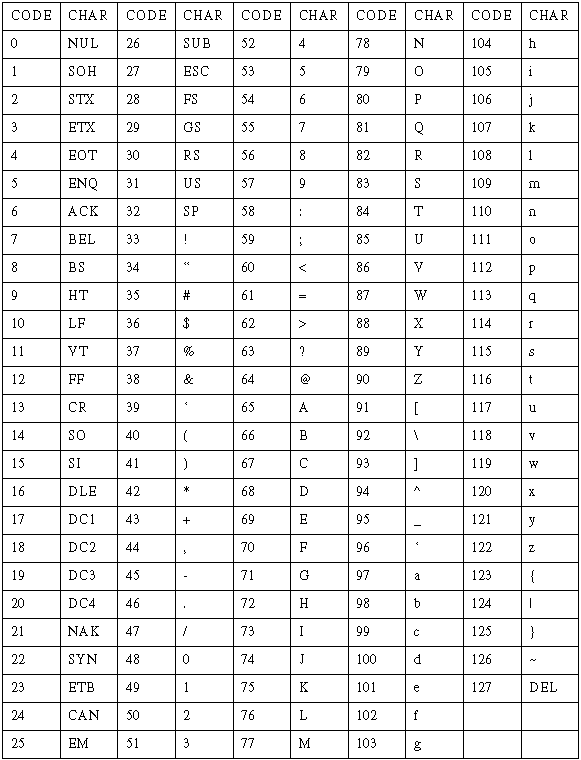
Copyright 1996